Tag Archives: plc

Finding Internet-Connected Industrial Automation Devices

I think most people in our industry realize you shouldn’t connect industrial automation devices to the internet, but just in case you happen to think otherwise, here’s a quick explanation why (this is old news, by the way).

You may believe that things connected to the internet are relatively anonymous. There’s no web page linking to them, so how is Google going to find them, right?

It turns out it’s relatively easy to find devices connected to the internet, and it’s kind of like the old movie WarGames where the lead character, played by Matthew Broderick, programmed his computer to dial every phone number in a specific block (555-0001, 555-0002, etc.) and record any where a modem answered. That was called “war-dialing”. In the age of the internet, you just start connecting to common port numbers (web servers are on port 80, etc.) on one IP address at a time, and logging what you find. This is called port-scanning.

It turns out that you don’t even have to do this yourself. One free service called SHODAN does this for you, and records everything it finds at the common port numbers (web servers, FTP servers, SSH daemons, etc.) and lets you search it just like Google. It turns out that (a) most modern industrial equipment is including embedded web servers and/or FTP servers to allow remote maintenance, and (b) most web servers or FTP servers respond with some kind of unique “banner” when you connect to them, announcing who or what they are.

So, if you don’t believe that you shouldn’t be putting industrial automation equipment on the internet, here’s a little experiment you can run:

  1. Take a ControlLogix with an ENBT card and hook it directly to the internet, so it has a real IP address.
  2. Wait a couple of days.
  3. See if your IP address shows up on this SHODAN search page.

You could try the same thing with a Modicon M340.

This query for Phoenix Contact devices is particularly scary, as one of the links is a wind turbine! I was a bit scared once I opened it (it opens a publicly accessible Java applet that’s updating all the data in real-time), so I closed it. There was no password or anything required to open the page. At least the button that says “PLC Config.” appeared to be grayed out. Let’s hope that means it’s protected by some kind of password… and that it’s hardened better than every single major corporation’s website was this year.

Just want to say thanks to DigitalBond for pointing out this SHODAN search for all Advantech/Broadwin WebAccess deployments around the world too.
Functional Programming in Ladder Logic

There’s a lot of stuff that falls under the term “functional programming,” but I’m just going to focus on the “functional” part right now, meaning when you define the value of something as a function of something else.

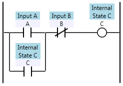
In ladder logic, we define the values of internal state (internal coils or registers) and outputs. We define these as functions of the inputs and internal state. We call each function a “rung”, and one rung might look like this:

Ladder diagram of Inputs A and B, and Internal State C

There’s something slightly odd going on in that rung though. You might say that we’ve defined C recursively, because C is a function of A, B, and itself. We all know, of course, that the PLC has no problem executing this code, and it executes as you would expect. That’s because the C on the right is not the same as the C on the left. The C on the right is the next state of C and the C on the left is the previous state of C.

Each time we scan, we redefine the value of C. That means C is an infinite time-series of true/false values. Huh?

Ok, imagine an array of true/false (boolean) values called “C”. The lower bound on the array index is zero, but the upper bound is infinite. C[0] is false (the value when we start the program). Then we start scan number 1, and we get to the rung above, and the PLC is really solving for is this:

Ladder logic defining C[1] as a function of A, B, and C[0]

If that were actually true (if it had an infinite array to store each coil’s value), then the ladder logic would be a truly functional programming language. But it’s not. Consider this:

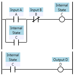
Two ladder logic rungs with inputs A and B, internal coil C, and output D

In all modern PLCs, the first rung overwrites the value of C, so the second rung effectively uses the newly computed value for C when evaluating D. That means D[1] is defined as being equal to C[1] (the current state value of C). Why is this weird? Consider this:

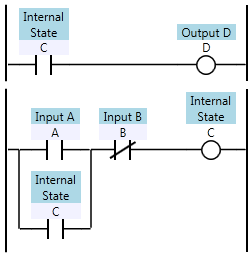
Two previous rungs with the rung order reversed

By reversing the order of the rungs, I’ve changed the definition of D. After the re-ordering, D is now defined as C[0] (the previous state value of C) rather than C[1]. This isn’t a trivial difference. In an older PLC your scan time can be in the hundreds of milliseconds, so the D output can react noticeably slower in this case.

In a truly functional language, the re-ordering either wouldn’t be allowed (you can’t define D, which depends on C, before you define C) or the compiler would be able to determine the dependencies and re-order the evaluation so that C is evaluated before D. It would likely complain if it found a circular dependency between C and D, even though a PLC wouldn’t care about circular dependencies.

There are a few of reasons why PLCs are implemented like this. First, it saves memory. We would have to double our memory requirements if we always wanted to keep the last state and the next state around at the same time. Secondly, it’s easier to understand and troubleshoot. Not only does the PLC avoid keeping around two copies of each coil, but the programmer only has to worry about one value of each coil at any given point in the program. Third, the PLC runtime implementation is much simpler. It can be (and is) compiled to a kind of assembly language that can run efficiently on single threaded CPUs, which were the only CPUs available until recently.

Of course this comes with a trade-off. Imagine, for a moment, if rung-ordering didn’t matter. If you could solve the rungs in any order, that means you could also solve the rungs in parallel. That means if you upgraded to a dual-core CPU, you could instantly cut your scan time in half. Alas, the nature of ladder logic makes it very difficult to execute rungs in parallel.

On the other hand, we can still enforce a functional programming paradigm in our ladder logic programs if we follow these rules:

  • Never define a coil more than once in your program.
  • Don’t use a contact until after the rung where the associated coil has been defined.

That means there should only be one destructive write to any single memory location in your program. (It’s acceptable to use Set/Reset or a group of Move instructions that write to the same memory location as long as they’re on the same or adjacent rungs).

It also means that if coil C is defined on rung 5, then rungs 1 through 4 shouldn’t contain any contacts of coil C. This is the harder rule to follow. If you find you want to reference a coil before it’s defined, ask yourself if your logic couldn’t be re-organized to make it flow better.

Remember, someone trying to solve a problem in a PLC program starts at an output and uses cross references to move back through the program trying to understand it. Cross referencing from a contact to a coil that moves you forward in the program doesn’t require any logical leaps, but cross referencing to a coil later in the program means you need to logically think one scan backwards in time.

Benefits

While ladder logic isn’t a truly functional language, you can write ladder logic programs in the functional programming paradigm. If you do, you’ll find that your outputs react faster, and your programs are easier to understand and troubleshoot.

More about Stuxnet, on TED

I’ve been enjoying a lot more TED recently now that I can stream it directly to our living room HDTV on our Boxee Box. Today it surprised me with a talk by Ralph Langner called “Cracking Stuxnet: A 21st Century Cyber Weapon”. I talked about Stuxnet before, but this video has even more juicy details. If you work with PLCs, beware; this is the new reality of industrial automation security:

Control System Security and 2010

Looking back at the year 2010, there was one really interesting and important happening in the world of industrial control system security: Stuxnet.

There’s a lot of speculation about this computer worm, but let’s just look at the facts:

  • It required substantially more resources to create than a typical computer worm (some estimates put it around $1,000,000, if you figure 5 person-years and the cost to employ specialized programmers)
  • It targets Siemens WinCC software, so that it can infect Step 7 PLCs
  • It looks like it was specifically targeted at a single facility (based on the fact that it was targeting a specific PLC, and only specific brands of VFDs)
  • It was designed to do real physical damage to equipment
  • It was designed to propagate via USB memory sticks to make it more likely to spread inside industrial settings, and even updated itself in a peer-to-peer manner (new versions brought in from the outside could update copies already inside a secure network)

If your average computer worm is the weapon-equivalent a hatchet, Stuxnet is a sniper rifle. There is speculation that the intended target was either the Bushehr Nuclear Power Plant or the Natanz Nuclear Facility, both in Iran, but what is known is that it has spread far and wide in other industrial networks. It’s been called the world’s first cyber super weapon.

What’s clear is that our industry’s relative ignorance when it comes to computer security has to end. Stuxnet proved the worst case, which is that a proprietary embedded PLC can successfully be the target of a computer worm.

I’ve been watching as more and more old-school vendors include Windows CE based devices as HMI components in their systems (like the PanelView Plus from Allen-Bradley). These are susceptible to the same kinds of threats that can infect Microsoft-based smartphones, and it takes a lot less than $1,000,000 to write one of those. It’s the kind some kid can put together in his basement for fun.

I’ve also seen (and even been pushing) a trend towards PC-based control. It’s nothing new, and I’ve seen PC-based control solutions out there for almost 10 years now, but it’s the networking that makes them vulnerable. In one facility about five years ago, I saw a PC-based control system completely taken down by a regular old computer worm. There were two mitigating causes in that case… first, the control system was on the same network as the main office network (the virus was brought in by an employee’s laptop that they connected at home), and secondly the vendor of the control software prohibited the customer from installing anti-virus software on the control system PC because they said it would void the warranty. I rarely see these same mistakes in new installations, but it does happen.

A couple of years ago I found a computer virus on an industrial PC with a VB6 application used as an HMI for a PLC/2. The PC in question was never connected to any network! The virus found its way to this computer over floppy disks and USB memory sticks.

Now if your facility is juicy enough that someone would spend $1,000,000 to take a shot at it, then you need specialized help. Stuxnet is a boon to security consultants because now they have a dramatic story to wave in the face of clients. On the other hand, most facilities need some kind of basic security measures.

  • Separate your industrial and office networks (if you need to move data from one to the other, then have a secure machine that can sit on both networks)
  • Make sure all machines automatically update their Windows Updates and their anti-virus definitions automatically, even if they’re on the industrial network
  • Change the default passwords on all devices and servers (including SQL Server’s SA password!)
  • Use different technologies in different layers (does your office network use Cisco managed switches? Consider using industrial managed switches from a different vendor in your industrial network)

Are you an integrator looking to expand your lines of business? Hire a computer security consultant and have them go knocking on the doors of your biggest customers with the Stuxnet story. You should be able to sell them a security assessment, and an action plan. Given the current security landscape, you’ll be doing them a big favour.

When to use a Sealed Coil vs. a Latch/Unlatch?

I just realized something I didn’t learn until at least a year into programming PLCs, and thought it would be a great thing to share for newer ladder logic programmers: when should you use a sealed-in coil vs. a latch/unlatch?

On the surface of it, a latch/unlatch instruction is sometimes frowned upon by experienced programmers because it’s correlated with bad programming form: that is, modifying program state in more than one location in the program. If you have one memory bit that you’re latching and unlatching all over the place, it really hinders readability, and I pity the fool that has to troubleshoot that code. Of course, most PLCs let you use the same memory bit in a coil instruction as much as you want, and that’s equally bad form, so I don’t take too strict of a stance on this. If you are going to use latch/unlatch instructions, make sure you only use one of each (for a given memory bit), and keep them very close together (preferably on adjacent rungs, or even in different branches of the same rung). Don’t make the user scroll, or worse yet, do a cross reference.

As you can imagine, if you’re going to use a Latch/Unlatch instruction and keep them very close together, it’s trivial to convert that to a rung with a sealed in coil, so what, if anything is the difference? Why have two sets of instructions that do the same thing?

It turns out (depending on the PLC hardware you’re using) that they act differently. On Allen-Bradley hardware, at least, an OTE instruction (coil) will always be reset (cleared to off) during the pre-scan. The pre-scan happens any time you restart the program, which is most importantly after a loss of power. If you’re using a sealed in coil to remember you have a pallet present in a zone, you’ll be in for a big surprise when you cycle power. All your zones will be unblocked, and you could end up with a bunch of crashes! On the other hand, OTL and OTU instructions don’t do anything during a pre-scan, so the state remains the same as it was before the power was removed.

For that reason, a latch/unlatch is a great indication of long term program state. If you have to track physical state about the real world, use a latch/unlatch instruction.

On the other hand, a sealed-in coil is a great way to implement a motion command (e.g. “attempting to advance axis A”). In that case you want your motion command to reset if the power drops out.

I hope that clears it up a bit. I always tried to avoid all latch/unlatch instructions until I understood these concepts.


Good Function Blocks, Bad Function Blocks

In case you’ve never read my blog before, let me bring you up to speed:

  • Write readable PLC logic.

Now, I’m a fan of ladder logic, because when you write it well, it’s readable by someone who isn’t a programmer, and (in North America, anyway) maintenance people frequently have to troubleshoot automation programs and most of them are not programmers.

That doesn’t mean I’m not a fan of other automation languages. I think structured text should be used when you’re parsing strings, and I like to use sequential function chart to describe my auto-mode logic. I’m also a fan of function block diagram (FBD), particularly when working with signal processing logic, like PID loops, etc.

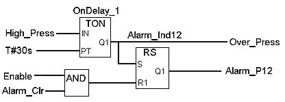
What I’m not a fan of is hard-to-understand logic. Here’s FBD used wisely:

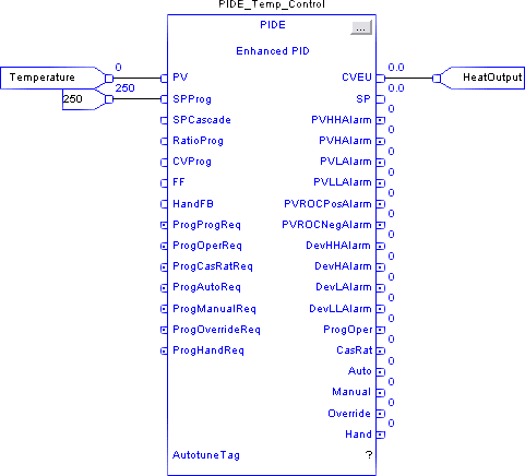
Here’s an example of FBD abuse:

I’m still reading Clean Code: A Handbook of Agile Software Craftsmanship by Robert C. Martin. He’s talking about traditional PC programming, but one of the “rules” he likes to use is that functions shouldn’t have many inputs. Ideally 0 inputs, maybe 1 or 2, possibly 3, but never more than 3. He says if you go over 3, you’re just being lazy. You should just break that up into multiple functions.

I think that applies equally well to FBD. The reader can easily rationalize about the first image, above, but the second one is just a black box with far too many inputs and outputs. If it doesn’t work the way you expect (and it’s doubtful it does), you have to keep going inside of it to figure it out. Unfortunately once you’re inside, all the variable names change, etc.

I understand the necessity of code re-use, but not code abuse. If you find yourself in the situation of example #2, ask yourself how you can refactor it into something more readable. After all, the most likely person who has to read this later is you.

Clean Ladder Logic

I’ve recently been reading Clean Code: A Handbook of Agile Software Craftsmanship. It’s written by Robert C. “Uncle Bob” Martin of Agile software (among other) fame. The profession of computer programming sometimes struggles to be taken seriously as a profession, but programmers like Martin are true professionals. They’re dedicated to improving their craft and sharing their knowledge with others.

The book is all about traditional PC programming, but I always wonder how these same concepts could apply to my other obsession, ladder logic. I’m the first to admit that you don’t write ladder logic the same way you write PC programs. Still, the concepts always stem from a desire for Readability.

Martin takes many hard-lined opinions about programming, but I think he’d be the first to admit that his opinions are made to fit the tools of the time, and those same hard-and-fast rules are meant to be bent as technology marches on. For instance, while he admits that maintaining a change log at the top of every source file might have made sense “in the 60’s”, the rise of powerful source control systems makes this obsolete. The source control system will remember every change that was made, who made it, and when. Similarly, he advocates short functions, long descriptive names, and suggests frequently changing the names of things to fit since modern development environments make it so easy to rename and refactor your code.

My favorite gem is when Martin boldly states that code comments, while sometimes necessary, are actually a failure to express ourselves adequately in code. Sometimes this is a lack of expressiveness in the language, but more often laziness (or pressure to cut corners) is the culprit.

What would ladder logic look like if it was “clean”? I’ve been visiting this question during the development of SoapBox Snap. For instance, I think manually managing memory, tags, or symbols is a relic of older under-powered PLC technology. When you drop a coil on the page in SoapBox Snap, you don’t have to define a tag. The coil is the signal. Not only is it easier to write, it prevents one of the most common cardinal sins of beginner ladder logic programming: using a bit address in two coil instructions.

Likewise, SoapBox Snap places few if any restrictions on what you can name your coils. You don’t have to call it MTR1_Start – just call it Motor 1: Start. Neither do you need to explicitly manage the scope of your signals. SoapBox Snap knows where they are. If you drop a contact on a page and reference a coil on the same page, it just shows the name of the coil, but if you reference a contact on another page, it shows the “full name” of the other coil, including the folders and page names of your organization structure to find it. Non-local signals are obviously not local, but you still don’t have to go through any extraneous mapping procedure to hook them up.

While we’re on the topic of mapping, if you’ve read my RSLogix 5000 Tutorial then you know I spend a lot of time talking about mapping your inputs and your outputs. This is because RSLogix 5000 I/O isn’t synchronous. I think it’s pointless to make the programmer worry about such pointless details, so SoapBox Snap uses a synchronous I/O scan, just like the old days. It scans the inputs, it solves the logic, and then it scans the outputs. Your inputs won’t change in the middle of the logic scan. To me, fewer surprises is clean.

I’ve gone a long way to make sure there are fewer surprises for someone reading a ladder logic program in SoapBox Snap. In some ladder logic systems, the runtime only executes one logic file, and that logic file has to “call” the other files. If you wanted to write a readable program, you generally wanted all of your logic files to execute in the same order that they were listed in the program. Unfortunately on a platform like RSLogix 5000, the editor sorts them alphabetically, and to add insult to injury, it won’t let you start a routine name with a number, so you usually end up with routine names like A01_Main, A02_HMI, etc. If someone forgets to call a routine or changes the order that they execute in the main routine, unexpected problems can surface. SoapBox Snap doesn’t have a “jump to page” or “jump to routine” instruction. It executes all logic in the order it appears in your application and each routine is executed exactly once per scan. You can name the logic pages anything you want, including using spaces, and you can re-order them with a simple drag & drop.

Program organization plays a big role in readability, so SoapBox Snap lets you organize your logic pages into a hierarchy of folders, and it doesn’t limit the depth of this folder structure. Folders can contain folders, and so on. Folder names are also lenient. You can use spaces or special characters.

SoapBox Snap is really a place to try out some of these ideas. It’s open source. I really hope some of these innovative features find their way into industrial automation platforms too. Just think how much faster you could find your way around a new program if you knew there were no duplicated coil addresses, all the logic was always being executed, and it’s always being executed in the order shown in the tree on the left. The productivity improvements are tangible.

The Two Kinds of Automation Software

As we all know, there are 10 kinds of people in the world.

For those of you who haven’t read Zen and the Art of Motorcycle Maintenance by Pirsig, he spends at least one chapter at the beginning talking about how we naturally tend to divide things into smaller pieces in an effort to understand them. The novice looks at a motorcycle and sees the visible things, like a seat, handlebars, and wheels, but the expert sees a fuel system, a cooling system, and the suspension. The same thing or system (motorcycle) can be subdivided different ways depending on what we want to do with it.

My tongue-in-cheek title of this post is an acknowledgement of the many ways we can categorize something like Automation Software, but for my purposes today, I’m making two categories: hammers and levels.

A carpenter carries both a hammer and a level, but the two have fundamentally different failure modes. If a hammer stops working, you’ll know it as soon as you try to use it. As long as it hammers in a nail, it doesn’t matter if the hammer is rusty, dirty, scratched or dented, it’s a working hammer. The level, on the other hand, is a measuring instrument. As novices, we assume that it comes from the factory pre-calibrated, and we happily hang our shelf or picture without testing it, but a professional carpenter knows that they have to check their levels for accuracy, or else the level is useless. You could use a level for years, but if one day it stopped being accurate, you probably wouldn’t know. This is a very different situation than the hammer.

Software in general, and automation software in particular, both have similar examples. You never need to “calibrate” the Axis 1 Advanced proximity switch on a machine because if it doesn’t work, the machine won’t make parts (and you’ll know about it instantly, usually via a 2 am phone call). On the other hand, testing data collection logic is surprisingly difficult because the only way to test it is to compare it with a known-good equivalent. Assuming you created this data collection logic to automate away a manual process, the only measuring stick we can check it against is the manual process we’re replacing. Once the system is bought off and we get rid of the paper system, how do you prove that subsequent changes don’t break the data collection system?

It’s tempting to brush off the problem by saying that anyone who makes a subsequent change has to do a full regression test of the system, including the data collection system, but anyone who has worked in a real factory environment knows that this is unlikely to work in practice. Full regression tests are expensive.

In the greater software world, they use automated unit tests. They take the logic being tested and they run it through a series of automated checks to make sure nothing changes. This works well in an environment like PC programming, but is very difficult in practice for PLC programming because (a) you usually need a physical PLC to execute the logic (unless you have some kind of emulator) and (b) the people maintaining the system are likely not familiar with concepts like unit tests, and are likely to undervalue their importance.

This screams for a system-level solution. Take accounting for instance. Double-entry accounting (the use of debits and credits to force every action to be made twice) is deliberately created to help catch manual entry errors. If your debits and credits don’t balance, you know you’ve made a mistake somewhere, and you go back and check your arithmetic.

In the automation world, the solution is to measure every input to the data collection system two ways, analyze and aggregate both separately, and compare the end results. Create a system warning or fault if the results don’t match. For instance, measure the amount of material going into the machine, and measure the amount of material exiting the machine, both as finished product, and scrap. If the input doesn’t match the sum of the outputs over the same time period, you know you have a problem. The system becomes self-checking (a hammer rather than a level).

If you follow this route, you need to take care to avoid some common traps:

  • Don’t re-use logic between the two sides (in fact, try to make them work differently)
  • Try to use different sensors or sensing methods (can we measure the input by speed and duration, and the output by parts and scrap weight?)
  • Record both, so if there is a discrepancy, you can check them against manual measurements

It sounds like more work, but making the system self-checking actually reduces the amount of testing you have to do, so it’s not as bad as you think. Besides, writing code is a lot more fun than testing it. We automate everyone else’s job, why not the boring parts of ours?

Reading the ControlLogix System Time in Ladder Logic

Since I’m in the tutorial mind-set right now, I thought I’d mention this little gem. Here’s how you can read the ControlLogix (or CompactLogix) PLC system time into a UDT so you can use the current time value in your ladder logic program.

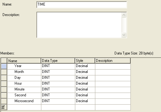
First I created a UDT called “TIME”:

RSLogix 5000 - Read System Time - UDT

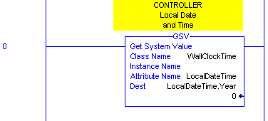
Then you just need to use the GSV (Get System Value) instruction with the WallClockTime class, and LocalSystemTime attribute to read the controller’s time into an instance of your UDT (here I created a new tag called LocalDateTime of type TIME). Note that I used the Year element of the LocalDateTime tag as the parameter, because that’s the first address of the tag. It starts writing there but fills in the entire UDT with the time values:

RSLogix 5000 - Read System Time in Ladder Logic

Now you can program your sprinklers to turn on and off in the middle of the night! 🙂


The Five Rung Logic Block

I’m still working on my RSLogix 5000 Tutorial, and I decided to include a brief introduction to a Five Rung Logic Block. If you’re like me, the first time you saw or heard about a five rung, you thought it was was a ludicrous amount of logic just to move a cylinder from one position to another. However, I realized most of my non-five-rung motion control logic always ended up being as complicated, or more complicated, than if I’d used a Five Rung from the beginning, so now I’m a convert.

A five rung block is named after the five coils that make up each block (these names differ between programmers and organizations, but they follow this pattern):

  • Safety
  • Precondition (aka Trigger)
  • Command
  • Complete (aka “In Position”)
  • Fault

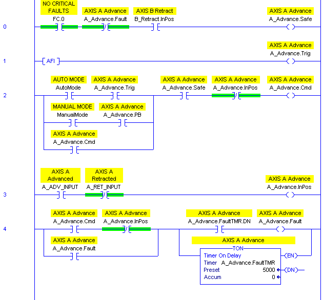
Briefly, your safety rung contains all the conditions that must be present during the entire motion. You put conditions like “no critical faults” here. You also put conditions such as interfering axes clear here. For instance, if axis A and axis B should never advance at the same time, then put A Retracted in the safety rung for the five rung that moves axis B to the Advanced position, and vice-versa. This is your “sanity check” logic.

The “trigger”, or “precondition” rung is the signal that will initiate automatic motion. You can put auto conditions directly in this rung, or you can tie in auto mode sequence logic from elsewhere. The difference between the Safety rung and the Trigger rung is that the Safety rung has to stay on during the entire motion, but the Trigger run only has to be true to initiate the motion.

The Command rung is usually a sealed in coil that turns on while the machine should be trying to move this axis to this particular position. Sometimes this is synonymous with an output itself, but in many cases the Command coil will then be used to drive one or more outputs or motion instructions.

The In Position (sometimes called “complete”) rung condition is the logic that interprets the sensors to tell us that we’re actually in the given position. It’s handy to use this coil throughout your program to indicate the state of the machine, rather than looking at the inputs directly. That allows you to invert input logic or add debounce logic later in just one place, rather than everywhere that depends on this machine state.

Finally, the Fault condition is normally a timeout fault. If the command coil is on too long without seeing the In Position signal, then we determine that the motion timed out, and we stop trying. We use this fault in our alarm logic as well.

Once the command condition becomes true, it’s normally sealed in until one of three things happens: the safety condition changes to false, the motion completes and the In Position signal changes to true (normal), or the motion times out and the Fault condition changes to true.

Here’s what a generic five rung logic block looks like. I left an AFI in the trigger rung because you normally come back and fill in that logic later. Note that this is only to move one axis to one position:

RSLogix 5000 Tutorial - Generic Five Rung Logic Block

The “PB” bit in the command rung is the HMI pushbutton that initiates motion to this position while you’re in manual mode. Note that both manual mode motion and auto mode motion have to follow the same safety conditions, but just have different trigger conditions.

You have to customize it for each situation. The contents of the safety and trigger rungs are obviously unique, but the command rung sometimes changes depending on the scenario. You may have more than just manual and automatic modes. Some automatic actions may actually happen when you’re not in automatic mode. Sometimes you may want an axis to “jog” (for instance a hydraulic axis moves slow, and you may want it only to move in manual mode if you hold your finger on the button) and in that case, you couldn’t seal in the Command bit around the manual mode pushbutton (you’d just seal it in around the trigger contact).

There are other variations. I hope you find this useful. If nothing else, when you come across this logic in someone else’s program, you’ll have a better idea of how it works.