This is part of an RSLogix 5000 Tutorial.
Understanding Asynchronous I/O
It’s important that you understand the difference between synchronous and asynchronous I/O in PLCs. If you come from the SLC 500 or PLC/5 world, you’ll be used to synchronous I/O, and that made your life a bit easier. In the PLC/3 world, I/O was asynchronous, and in a move that surprised many programmers, the ControlLogix/CompactLogix platform uses asynchronous I/O as well.
In a SLC 500, the PLC “scanned” the inputs by reading the state of the hardware and storing them in memory. Then it solved the logic. Then it “scanned” the outputs by copying the output coils to the actual hardware outputs. The important thing to realize is that the state of an input could never change during the logic solve. That meant you could write things like this:
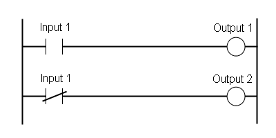
…and you could be certain that Output 1 and Output 2 would never be on at the same time. However, with asynchronous I/O, our assumptions are wrong. Both Output 1 and Output 2 could be on during the same scan, or off during the same scan if Input 1 changes state between the time that it solves the first rung and it solves the second rung. Rare, but possible, and it leads to bugs that are intermittent and very hard to find, especially in logic that deals with critical timing, like data collection or communication logic.
In the days of the PLC/3, I understand programmers used to make sure they didn’t use any input more than once. They would copy the state of the input to an internal coil if they had to use it in more than one rung. With RSLogix 5000, I suggest solving it by creating a MapInputs routine that “scans” your inputs into temporary coils at the beginning of your program. Then you can forget about synchronous/asynchronous and go about your business.
Contact and Coil
Faced with the problem above, what I see a lot of programmers do is define a UDT for each input card, and then use a copy instruction to move the hardware input state into the UDT tag. There are two problems with this: first, UDTs can’t be edited without downloading the processor, so if you change an input you have to stop the machine, and second, if you’re using the UDT tag in your program, you can’t force those bits directly. You have to find the input bit that corresponds to the UDT tag bit, and force that. How would you go about finding that input? You can easily right click and do a cross reference, but that only brings you to the copy instruction. You still have to figure out that you’re looking at the 5th bit in the UDT, and then you know it corresponds to output 4 in the I/O card. Quite painful when you’re trying to fix a machine.
The solution is to use a separate rung for each input: a contact for the “real” input and a coil for the “internal” input that you use in your program. If you right click on the internal input in your program and pull up a cross reference, you can always find the OTE instruction, and easily find the real input bit to force.
Does it seem like a lot of work to do this? It really isn’t, especially if you master the art of copy-paste-search-replace, and the first time you have to find the input you’re looking for, you’ll save yourself at least that much time.
Back to the Tutorial
When we finished the last section of the tutorial, we had created a MapInputs program, but it still looked like this:
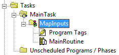
Following the naming convention from the last section of the tutorial, rename MainRoutine to Aa_Main (by right clicking, selecting properties, and editing the name, then clicking OK). It’s already configured as the Main routine of the MapInputs program, so we don’t have to do that.
Right click on the MapInputs program and choose New Routine… from the menu:
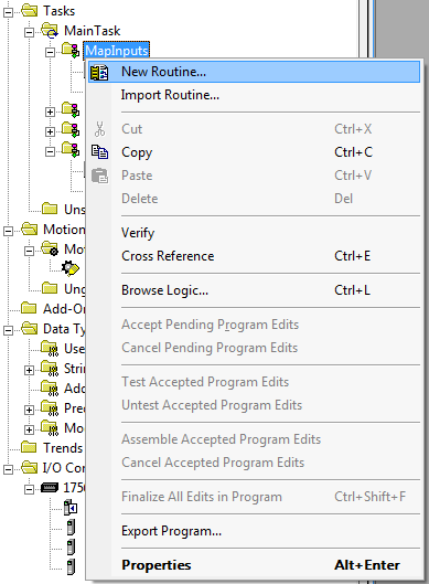
That will open the New Routine dialog box. We want this routine to hold the logic for mapping the local input card that we added in section 3 of the tutorial. We named the I/O card “LI01” (for Local Input card 1). Name this routine the same, for consistency:
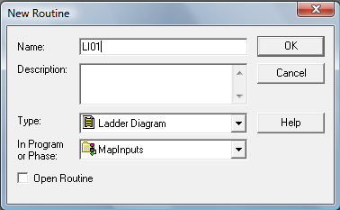
Click OK to finish creating it. You’ll now see LI01 in the controller organizer:

Follow the instructions from the last tutorial section to edit the Aa_Main routine in MapInputs and add a JSR instruction to call the LI01 routine:

Now open the LI01 routine:

Add a contact and a coil to this empty rung. Locate the toolbar above the ladder editor, and click the contact button, and then the coil button (highlighted):

That should change the rung so it looks like the following:

When you created the LI01 input card in the I/O configuration, RSLogix 5000 automatically created some tags in the Controller Tags section for access to the inputs of this card. The tags begin with the word “Local”. The first input of the card is “Local:1:I.Data.0”. That means local rack, slot 1, input data, bit 0. Select the question mark above the contact in the new rung, and enter this full tag name. You should see it above the contact now:

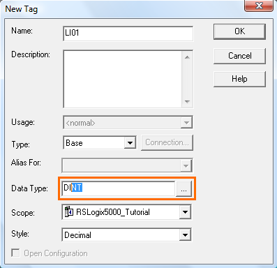
That’s the input side. Now we need an internal coil to store the value of the input during the scan. Rather than creating individual boolean tags for each coil, I suggest creating a single DINT tag called LI01 and using LI01.0 (bit 0) for the first input, LI01.1 for the second input, etc. I would go as far as using these tag names as the input wire names in your electrical drawings.
Select the question mark above the coil, and type LI01.0 and press enter:

Notice that the rung still has errors. This is because we haven’t defined the LI01 tag yet. If you hover over the tag, it will say “Undefined Tag”. To define the new tag, right click on LI01.0 above the coil and select New “LI01” from the context menu:
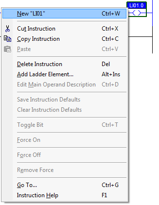
That will open the New Tag dialog and autopopulate the Name field with LI01. However since we defining a tag based on a Coil instruction, it defaults to a Boolean data type. Change the data type (highlighted) to DINT (a DINT is a double-integer, meaning it has 32 bits – it is the default word size in the processor):
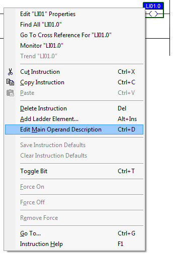
Click OK, and the rung won’t show an error anymore. However, even though LI01.0 is a perfect name for a tag because it’s concise and consistent, we also need to add a description so we know what it is. Right click on LI01.0 above the coil again, and this time select Edit Main Operand Description from the context menu:
That will open a small window above the ladder editor where you can enter a description. Go ahead an enter “INLET Cold Water Valve On”:
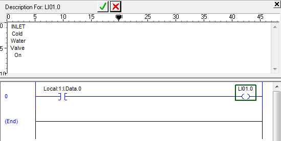
Click down in the ladder area when you’re done, and the description editing window will close. That will leave you with your first complete rung in the LI01 routine:

Add 15 more rungs to this routine in the same way, except increment the last number in Local:1:I.Data.XX from 0 to 15, and the last number in LI01.XX from 0 to 15. You can add the descriptions for the coils that you see here:
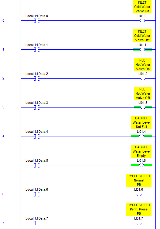
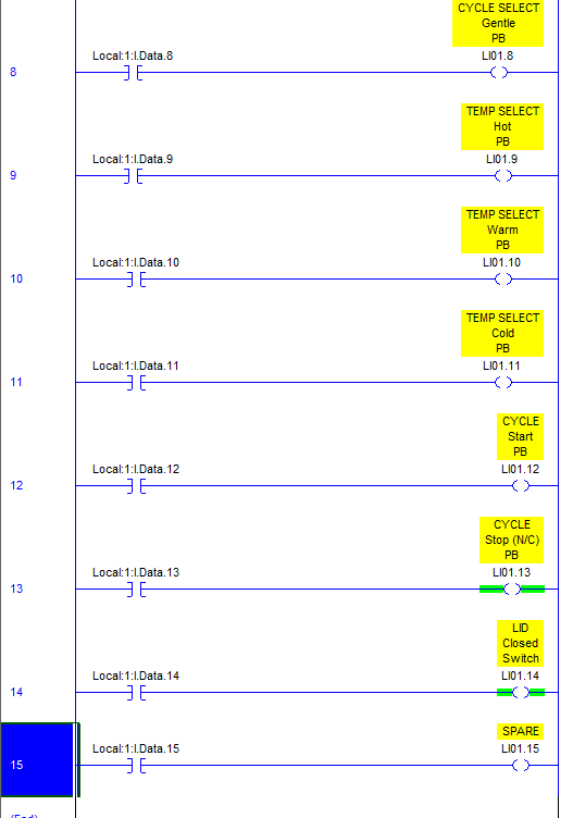
That’s all the inputs we’re going to have for this tutorial. If you had more input cards in your application, you’d add more routines in the MapInputs routine and more DINT tags for holding the state of the inputs during the logic scan.
Next time I’ll describe how to map your outputs, which is actually a bit different.
First of all, thanks for taking the time to write this tutorial, I’ve been looking for some sort of instruction to get me started programming in ladder logic on RSLogix 5000 and this has been a big help, especially your explaination as to why you write things the way you do.
I’ve worked through every step of the tutorial today and in doing so I noticed that you only create the LI01 tag in the MapInputs program – for this tag to be used in the other programs (I first noticed this when writing the Fa_Critical routine in the Faults program) I copied the entry for LI01 in the tag explorer and pasted it into the Program Tags section for each of other programs. Later on I found that I had to do the same with the FC tag created in Fa_Critical in order to reference it in Bc_CycleStart of the WashingMachine Program.
I am not quite sure if this was the right thing to do, but it seems to work okay for the time being – whether the contents of tag are passed between the different programs is something I haven’t tested so far.
Once again, thanks for writing the tutorial, I hope you findthe time to finish it soon.
Hi Chris,
When I create the LI01 tag, take care to notice the “Scope” box on that dialog. I have it set to RSLogix5000_Tutorial, which should make it a controller tag. By default, the first time you create a tag, it will create it as program scope, so you have to change this to controller scope. Once you do that, I think all subsequent tags will default to controller scope.
You can separate your tags out into controller and program scope. LI01 should definitely be controller, since it represents I/O which affects everything. I hope that helps.
– Scott
At least the fix is simple! All I needed to do to correct my mistake was copy paste the LI01 and FC tags into the controller tags database, then delete the entries I previously created for them in the relevant programs tag databases, acknowledging that this will cause the tag references in each routine to now refer to the newly created controller tags. If only variable management was this simple and explicit in all programming languages!
Thanks for this tutorial, I am integrator and I have experience in Micrologix, SLC500 and PLC5 but, it is the first time that I have to work with platform Controllogix. This toutoria has been useful for me.
Thanks a lot.
Thanks for tips!
I’ve never seen your method before (seen lots of programs so far), I admit I also used CPS instruction.
Question related:
If you have a UDT and want a “alias” to a IO point from a member (which you can’t now) which option will you describe as best use:
1- directly in IO map routine XIC+OTE to UDT member, or
2- XIC+OTE from mapped Input to UDT member? IF this one, in same routine? Right under mapped input assigment?
@ivirban – If you feel you need to organize your I/O into UDT, then I suggest replacing the LIxxx DINT’s with your UDTs, and just use XIC+OTE to go right to the UDT. However, I caution against using UDT’s at all for this because you can’t edit a UDT without downloading the CPU. That’s the reason I used a stand-alone DINT for each input card. It provides more flexibility when you’re online.
I’ve always used Function Block Diagrams for my I/O buffering. It’s nice because it looks like a wiring diagram and is easy to locate the physical I/O for forcing purposes.
I have read some just right stuff here. Definitely price
bookmarking for revisiting. I surprise how so
much attempt you set to create the sort of excellent informative web site.
Wanted to get your opinion on something. I have an operator pedestal for selecting and starting cycles, and also an HMI on the other side of the machine for loading recipes. The HMI will also have the ability to mimic the inputs of the pedestal so that a cycle can be started from there. What makes more sense:
a) Mapping the HMI input as a branch rung under the corresponding local input in the MapInputs task
b) Mapping the HMI input as a branch rung under the corresponding LI01 bit in the Bc_CycleStart routine in the Machine task
c) Having buttons in the HMI associated with the LI01 tag used as outputs in the MapInputs task
I hope that made sense. I’m interested to hear your thoughts. Thanks.
@CevinMoses – option (b) is almost certainly your best option. Someone reading your program will assume that the LI01 bits are proxies for the inputs directly, so to mess with them without a really good reason (like a debounce) is going to invoke confusion. You want someone looking at your logic to see that there are two things that can start this cycle: the hard-wired button or the HMI button. They will definitely want to see that.
Your option (c) is overly complicated.
Typically what you’ll see is a tag called HMI_CycleStartPB. The HMI will write to that tag, and you can use it to branch around where you use your existing cycle start PB. The tag name itself tells the reader that the signal is coming from the HMI, and that it’s a button.
This was very helpful. I have a miss matched mess of an io tree that has been added to multiple times, and everything was aliased to a raw table with a loop to populate it. could never find anything and very slow! I have started down the path of AOI’s for all IO, and trying to get it mapped correctly was horrendous as i am not an electrical engineer or such and my first attempt at the IO rather than just logic routines. this was very helpful information on the physical io properties.
Thank you.
Great article!
I’m a novice programmer. Mapping digital Inputs seems like great method. However, with the most recent version of RS Logix5000, it has a “Parameters and Local Tags” which seems to me, a new way of buffering IO. Considering design, memory use, scan time, and troubleshooting, is this new feature a better way to go?
Also, does it make sense to use your method with Analog Inputs?
Thanks again for creating this tutorial, it’s a nice gem to reference!
Great tutorial, Thanks. Could you please clarify one thing for me? As much as I like the I/O mapping, I feel as if alias will achieve the same goal. Ofcourse with I/O mapping we can control the program flow better but since the option is available, is there any other reason why you can’t/shouldn’t use alias tags instead of mapping?
Thanks in advance.
Silly me, I skipped your info on asynchronous I/O. I just read it and answered my question but if there is any other reason/explanation or example, then please share
Thanks
@HR – there are actually two reasons: one is the asynchronous I/O reason, but the more important reason is to create a single point where you can add more logic for each input. It’s saved me a few times where I had a problematic input and I wanted to add a debounce timer or some other conditioning logic. This gives you a single place to do it.
@Jake – When I’m using analog inputs, I also usually put the input scaling (converting from raw counts to engineering values) in the input map routine.
just to clarify, are all of these “mapped” inputs LI01.XX from 0 to 15, physically wired to inputs? I see that some of them have both states defined – INLET Cold Water Valve On is LI01.1 and INLET Cold Water Valve Off is LI01.2 on Local:1:I.Data.0 and Local:1:I.Data.1, respectively.
How can this be? I am using your tutorial to set up a simple push button/LED and don’t understand why I would want to have both states mapped to a location on the input card when I could read the state and make a decision.
(coming from the world of microcontrollers, PLCs seem counter intuitive).
Thanks for your clarification.
Note to avoid problems along way with the tutorial note that the scope of the LI01 tag is not local to the routine, rather it has a controller scope
I’ve just started trying to teach myself a few different programming languages, and tutorials like this are a huge help. All the screenshots you provided are really clear and helpful! I learn so much better when I can follow along like this than I do when I have to watch videos. Actually, I’m thinking about taking short RSLogix 5000 training course. Learning how to deal with the asynchronous I/O in the ControlLogix/CompactLogix platform should give me a good headstart.
I disagree with this mapping procedure. I’ve run into programs like this with horrific results. The engineer that writes the program has left the company and took the program with him. He’s one of those guys that likes job security and doesn’t share his information. Now something happens to the machine and you have no recourse but to upload the program. You don’t get all of those comments with the upload. Just the tags. So you don’t have a clue what any of that means. Use descriptive tags and alias them to the IO. Then everyone can understand what the program is doing. Share and backup. Don’t be one those guys!
@Warren – I have never run into a problem with missing comments in a place where I’ve worked, because any place I’ve worked understands the importance of having the original program. Years ago I ran into a place that had purchased a machine and didn’t have the PLC source code, so they paid me to go there for a day, going through the prints and the wiring, figuring out what it did, and writing comments for all the bits in the PLC (this was a SLC, not a Compact/ControlLogix).
The idea that you might someday run across a program without comments is hardly a reason to write all your code without using comments.
How can I include a new analog card to an existing project on Logix5000 environment and use the tag of the analogue signal to automate the control of a valve.
I’ve already done the hardware installation and configured the I/O device on the device configuration. but I find it difficult to locate or create the right tag to use on the rung for the project.
kindly assist. thanks
Hmm – If I set the Datatype of the coils to DINT as shown in the tutorial I get an error on the rung telling be I have data type mismatch. If I leave the coils as teh default BOOL Datatype all is good.
@Bruno – Hi, try creating a DINT tag called “LI01” and then in the coil use “LI01.0” which is bit zero of the DINT tag.
Hi,
I took a recent tutorial for RSLogix5000. He segregates his IO first as he says it’s easier to make changes later on. Each IO has a binary address as he reckons it’s best practice. so an I:0/0 goes to a B3:0/0.
] [ I:1—————-( ) B3
] [ B3—————-( ) O:2
But I’ve seen coding written in a different way. Am I on the right track?
Why not simply use copy CPS Source Local:1:I.Data to Dest LI01 ?
@Phi – Inside my program, if I use LI01.0 somewhere, I want to be able to right click on it, do a cross reference, and find the rung where it’s used as a coil. On that rung, I can find the contact on the left, which is the actual input, and I can right click and force it. If I used a CPS instruction, then I wouldn’t be able to find the input and force it so easily.
Love this, the last three compressor stations I was assigned to had rslogix 5000 and studio 5000 programs that all had mapped I/O like yours and it is so much easier to change a bad input on a card without changing anything else. Now I’m at a different station and they have alias tags for I/O and nothing is mapped. Its like the twilight zone lol. Thanks for all the work you’ve done here.
10 years later, & I still find your tutorials relevant and very useful!
Thanks, Scott…for the gift that keeps on giving!
Hi and thanks for great tutorials which still are a great resource a decade later.
Coming from the Twincat world, I have a couple of questions:
1) Why not use an array of BOOL for LI01 rather than a DINT?
2) Why separate inputs for valve on and valve off? (LZ already asked 4 years ago but I don’t see a response)
@EBJ – Since I would typically want to see the input tag referenced on either a wire label and/or a lamacoid device tag, I’d rather use LI01.3 than LI[1][3] or LI01[3] because the dot notation is far more common in industrial wiring, printers, and engravers. Not that it can’t be done, but it certainly looks wrong. Also if you’re ever concerned about space, depending on the processor you use, LI01 is a DINT and takes up one 32-bit word of memory, but LI01[3] takes up either a byte (Allen-Bradley) or 4-bytes (on something like TwinCAT) so arrays of bytes are much less space efficient. If you’re reading this array of bytes into an HMI it’s going to be much slower. Those are my reasons, they may not all be valid in your case. For (2) a valve can get stuck half way, much like a pneumatic cylinder. You sometimes want to sense both positions to make sure it’s working. This also gives you redundancy, so if one of the sensors fails, you’ll be able to detect the condition when both are on, or both are off for some length of time.
Very good tutorial and still very relevant even though it’s been more than 10 years. Clear and detailed explanation. I’m waiting for your tutorial Maping IO Analog Card. Have you made it? Give me a link