This is part of an RSLogix 5000 Tutorial.
So in the last section we created the low level machine control routines, but we left AFI instructions as placeholders where we needed to insert commands from our automatic mode logic. We did that first because in real life you rarely have enough time to completely write a program before you have to commission it. Real projects have many things going on in parallel, such as design, programming, ordering, panel building, mechanical assembly, electrical field wiring, checkout, commissioning, etc. You need to be ready to download your program and start the electrical checkout long before you have enough time to finish programming the machine.
At this point, you already have all of your low level machine control (and hopefully your HMI manual mode screens) laid out, so you can actually download the program to the PLC and start assisting with the checkout. (Then you can write the rest of your program in the hotel room at night.)
State Machines
When you write auto mode logic, whether you realize it or not you’re creating a finite state machine. Before the advent of PLCs this was done with drum sequencers. When PLCs were invented, they created the sequencer instruction as a way to port existing mechanical drum sequencer logic into the PLC. Don’t use sequencers. They’re extremely difficult to troubleshoot, especially for someone who only knows basic ladder logic.
You can create readable finite state machines in ladder logic, and I’ve certainly done that on occasion. However, state machines are easier to write and troubleshoot if you can express them as state transition diagrams or flowcharts. Thanks to the IEC 61131-3 specification, RSLogix 5000 now includes the sequential function chart (SFC) language which is kind of a cross between the two. It’s perfectly suited to laying out your auto mode logic.
Add a new Sequential Function Chart Routine
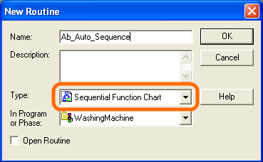
Start by adding a new SFC routine to our Washing Machine program. Right click on the Washing Machine program and click New Routine. In the dialog that pops up, enter the name Ab_Auto_Sequence, but remember to select Sequential Function Chart in the Type drop down box:
Double click on the new routine to open it:
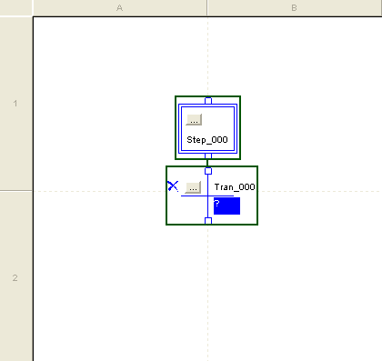
If you’ve never seen an SFC routine before, this might be a little overwhelming, but it’s pretty simple. The top rectangle is a “Step”. The fact that it has a double border means it’s the Initialization step for the SFC. This means that we always start our sequence here. The little cross mark under the step is a Transition. We attach a True/False condition to the Transition, and when the condition is true, we move from the step before the transition to the step after the transition.
These sequential function charts have a lot of advanced functionality, but I want to show you what I think is the simplest and most powerful use of them… just think of every step as a bit, or boolean condition, that’s only on when that particular state is active. So, we’re going to make a bunch of steps (Step 1, Step 2, Step 3), and each one represents a bit that will turn on only while that step is active. We’ll use that bit in our lower level machine control routines elsewhere in the Washing Machine program. You can also use BOOL tags directly in your transitions, which means you can drive the transition logic from ladder logic conditions if you like. If you want, you can also use Structured Text language expressions here too, like “NOT(SomeBOOLTag)”.
As you can see, the editor provides an initial state for us, but doesn’t include a Stop condition. We need a Stop condition to tell the sequential function chart when the auto sequence is complete (so we can re-start the sequence). Let’s create one now. First select the Transition element, then click the Stop instruction on the tool bar above the editor:
![]()
That inserts the new Stop instruction and attaches it into the diagram after the transition:
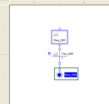
Every time you create an SFC instruction, it automatically creates a tag to store the instruction state. This is a nice feature, and beats having to create each coil tag by hand, like we do during ladder logic programming. However, you’ll quickly realize it always creates the tags in Program Scope, not Controller Scope. That’s not a bad idea actually, and I’ve always left them in Program Scope because I only ever reference these tags from the low level machine control routines inside the same program.
By default it gave the new instruction (and tag) a name of Stop_000. Change that by right clicking on the Stop instruction and selecting Edit “Stop_000” Properties from the context menu. That displays your normal Tag Editor dialog box, and you can edit the tag name. I suggest changing it to “Stop” because we’ll only have one Stop element in this chart.
Call the new Sequential Function Chart Routine from your Main Routine
Executing the SFC routine is a little more complicated than just inserting a normal JSR instruction like we do for ladder logic routines. First of all, SFC routines need to be reset by external logic when they hit a Stop instruction, and secondly we need to reset the sequence from time to time in order to recover from faults or mode changes. Here’s the logic from the Aa_Main routine for calling the sequential function chart routine:
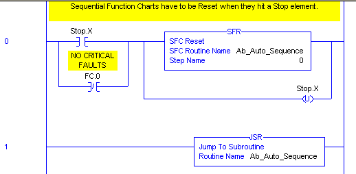
As you can see, we use the SFR instruction to reset the chart, but we also have to unlatch the Stop.X bit, which is set if and when the chart reaches the Stop instruction. When we execute the SFR instruction, the chart resets its state to the Initialization step (the one with the double border on it).
We’re resetting the SFC any time we have a critical fault. You may also want to reset it any time we’re not in Auto Mode on a normal industrial machine. You can add additional conditions here, as necessary.
Let’s Get This Sequence Started
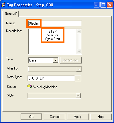
I started by renaming Step_000 to StepInit, and I added a description:
This description shows up as a little comment box beside the step:
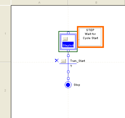
You can reposition the description box by clicking and dragging it anywhere you want in the chart. You’ll notice I also renamed the transition from Tran_000 to Tran_Start.
Now we need to enter a condition for the Transition. We need to specify a boolean condition that initiates the sequence. In this case, let’s use LO02.10 (Cycle Running Pilot Light output). That only gets turned on when the automatic sequence starts. Start by selecting the question mark under the transition name, and then start typing the BOOL tag: LO02.10 (the second character is the letter ‘O’, not a zero):
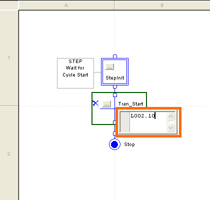
Once you’ve finished entering the tag name, click outside the editing box and it will accept the tag. Note that the tag name is red. This means it’s False, or off. During debugging the condition turns green when it’s true. While you’re online, the steps also highlight with a green border when they’re active, so it’s easy to figure out where you are in the sequence. (You can also do online edits in SFC, just like in ladder logic.)
Step by Step…
Adding new steps is a breeze, particularly if you have a very sequential (as opposed to parallel) sequence. To add a new step after the initialization step, start by selecting the Transition (Tran_Start) and clicking the new Step button on the toolbar:
![]()
That adds a new step after the transition, but before the next element (the Stop instruction):
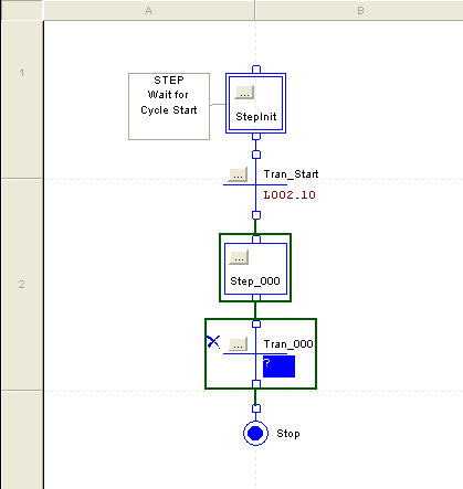
That’s basically all you need to know. Keep creating steps, setting their name and description, and setting the transition condition. The Step instruction creates a tag to hold its state. The tag has a .X tag member (such as StepInit.X) that’s set to True when the step is active. You can use this in your ladder logic to take actions during this step.
Our Washing Machine program only has sequential logic, but I wanted to discuss parallel execution paths for a moment. SFC offers the choice of either alternative paths (sequence A or sequence B), or parallel paths (sequence A and sequence B at the same time). These correspond to the Selection Branch Diverge, and Parallel Branch Diverge instructions, respectively:
![]()
In the next section I’ll discuss how to tie this SFC logic into your low level machine control logic.
great tutorial i’ll hope take de next tips for programming grafcet in rslogix 5000 thanks.
Great tutorial, really.
Hope to see the next part soon!
I have been using SFC for a couple of years, and came across this article. Very informative.
Thanks.
Thank you a lot! Its so hard to understand american way of thinking (in RSLogix), after user frendly Siemens software…
This is a great tutorial for getting started in the series 5000 PLC’s. I’ve previously used another brand (koyo), and bought an old AB 1769-L30 in order to familiarise myself with the series 5000. It’s quite a different way of working and I especially appreciate your recommendations on a workable style.
Eventually expanding the tutorial to cover a SCADA system monitoring and controlling the PLC would be really something special.
The only thing that doesn’t work for me is the state logic diagrams, but that’s due to my ancient machine not supporting anything but ladder logic.
Excellent!!
“Once you’ve finished entering the tag name, click outside the editing box and it will accept the tag. Note that the tag name is red. This means it’s False, or off. During debugging the condition turns green when it’s true”
I’ve never known a transition’s tag to turn green when it’s on. What am I missing?
@Korda Mentu – I get intermittent results. Sometimes it works and sometimes not. More recently, I don’t remember it working either. Might be worth contacting AB to see what it’s supposed to do.
Hi I’m loving your tutorial. Thanks.
When will you upload the last part of this RSlogix5000 tutorial because it has been several years now.
Please do it soon.
Thanks again
Sincerely
Jay
ok where do I go from here, the last thing stated in the tutorial, said: the next step is to tie the/this sfc into your low level machine control logic. ?????
I did not see anywhere else to proceed ?? thanks Larry Davis2694872735
Really great tutorial !
Hello!
Qustion: Is it really a good idea to reset the SFC if a critical fault occurs? I mean dont you want to know which step the machine faulted at?
Thanks for a great website!
Hello Scott!
You have the talent to explain difficult things in plain, understandable language.
This is not for everyone. Why did you stop your lessons? They are very necessary. Please continue them or advise other lessons of the same high level.