This is part of an RSLogix 5000 Tutorial.
Someone recently said to me, “what we needed on that project was more planning and less complaining about what we couldn’t do.” Perhaps it’s fitting that we’re on step 9 out of 12 of this tutorial, and we’re only now about to write some actual logic. PLC programming, just like PC programming, is all about having a place for everything, and everything in its place. That takes planning.
When you write logic, you’re making a commitment that’s expensive to undo. Planning, structure and architecture are about building a strong foundation that’s going to support more than you initially intend to build on it. What I’ve presented in the tutorial up to this point is an architecture for your program that can grow with your program without becoming unwieldy and hard to maintain.
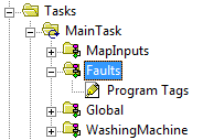
We already created a Faults program previously in the tutorial:
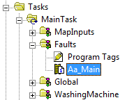
Start by adding an Aa_Main routine and setting it as the main routine of the Faults program like we did previously in the tutorial:
Fault Severity
Faults are any condition that stops the machine from operating. It’s normal to break down you faults into different levels of severity:
- Critical
- Normal
- Warning
You have to come up with your own severity levels based on your needs. These should correspond to how your machine will react when a fault occurs.
For instance, I normally differentiate between critical faults and normal faults like this: a critical fault requires the machine to stop immediately and a normal fault requires the machine to stop after completing the next cycle. It’s obviously better to stop at a nice stopping point, like a home or pounce position if you can, so you want more faults in the normal category than in the critical category.
Examples of critical faults:
- An emergency stop signal is received or guard door is opened
- Loss of communication to I/O modules
- Loss of encoder feedback signal (you can’t finish the cycle if you don’t know where you are)
Examples of normal faults:
- Sequence fault (expected part A but detected part B)
- Low air pressure signal
- Motor over-temperature signal
Which fault goes in which category is completely dependent on your application. If you have a very long cycle time, you may want to make an over-temperature fault into a critical fault because you can’t safely finish the cycle without causing damage.
Warnings generally don’t cause the machine to stop. In some sense they’re not faults at all, but we piggyback them on the fault system because we normally have an alarm system built on top of the fault system and we want warnings to show up as alarms on our operator interface. A warning might be something like “it’s time to change the oil filter”.
Fault Zones
In addition to fault categories, you also need to consider fault zones. For instance if you’ve separated your machine into different zones correctly, then some faults should only affect one zone, not the whole machine. It’s quite normal for one fault to be a critical fault in one zone, but be a normal fault at the machine level. For instance, if you have an assembly line with 10 stations, losing the encoder feedback on an axis at station 3 might be a critical fault for the station 3 zone, but would only be a normal fault for the machine, which would allow the other 9 stations to finish their cycle. On the other hand, receiving and e-stop signal or losing the communication bus that services the entire assembly line are machine level critical faults that should immediately stop all stations.
Alarms
We sometimes think of alarms as synonymous with faults, but that’s simply not true. A fault is an internal condition of the machine that may or may not cause various actions. An alarm is simply a message to the operator to notify them of an action they need to take. These are fundamentally different, but it’s also good practice to setup your faults so you can have a one-to-one mapping between faults and alarms. For instance, if you have a fault called “motor over-temperature”, you’ll likely want an alarm for this condition as well. However, I would suggest phrasing the alarm more like an instruction: “Motor Over-temperature Fault (number XXX), wait for 2 minutes, then reset the fault and restart the machine. If this fault occurs again, call maintenance.”
Now our washing machine example is a relatively simple machine. We don’t have much of an operator interface and the sequence is so simple and completely automatic that if something goes wrong there’s nothing the person using the machine can do except call a technician. Therefore we’re going to categorize everything as a critical fault, and there’s only one zone: the machine.
Create a second routine in the Faults program called Fa_Critical:
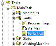
If you have more than just critical faults, you could add Fb_Normal and Fc_Warning routines, or whatever you need. The “F” prefix denotes faults in this case. You might have “F” routines in other sections of your code too, if you need to categorize your faults into fault zones. It’s best to implement that categorizing logic in the zones themselves.
Remember to open Aa_Main and add a JSR instruction to call the Fa_Critical routine:

Now open the Fa_Critical routine. For readability, it’s nice to start off the routine with a summary rung that creates a “no faults” bit. Now if you wanted to create an “any fault” bit, you’d have to OR together all the fault conditions with parallel branches, and that means the rung is going to get really tall in the vertical direction, meaning you’ll have to scroll more. The power of online PLC programming is the ability to monitor the status while it’s running. I prefer not to scroll unless absolutely necessary, and I like having as much information on the screen at once as I can. Therefore I prefer the following type of structure:
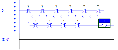
So the logic is: if not fault 1 and not fault 2 and not fault 3 … etc. … then I have no faults (or in this case, no critical faults).
Now you may be thinking, “why would you put each individual contact in that rung? Why not just put all your fault bits into DINT tags and then use EQU instructions to compare 32 bits at a time?” Well, then I’d say you haven’t been listening to anything I’ve been saying about readability. Your program will be written once and read many times, and nobody’s going to be reading it for a little light bedtime reading. They’ll be trying to decipher it when the machine is down and the company is losing hundreds or even thousands of dollars a minute and a plant manager is standing over their shoulder yelling at them to make them go faster. They’ll be sitting there counting bits in your DINT tag and cursing your name. Trust me on this. If I can impart one useful piece of knowledge to you about programming in general, it’s this: NEVER try to save time while writing a program if that time comes at the expense of readability. Learn to use tools like copy/paste/search/replace or export the code to an L5K format and write scripts to edit it there, but never sacrifice readability. That would be like a painter buying the most expensive paint and then throwing buckets of it on the wall because it’s faster than rolling it on.
We’re going to need a bunch of bits to use to store our faults. An array of DINT tags is a good idea. Decide how many you need (256 is a common “round” number but it’s going to depend on your application). I suggest creating the tag array (let’s say an array of 8 DINTs) but skipping bit 0. You can use it as your summary bit, or you can just ignore it, but it’s good to start numbering your faults at 1, and it helps with the readability if your bit numbers line up with your fault numbers. It’s quicker to just put a generic description (“FAULT 001”) on the first bit (array index 0, bit 1), and then use the import/export feature to export that tag to a file, open it in excel, and create descriptions for all 254 other faults, then import it back in. Then you’ll have all your bits numbered correctly in the tag descriptions.
At the same time, I suggest creating a matching array of timers, because it’s so common to need timers in your fault logic, and it’s nice if the timer number matches your fault number. Therefore, create an array of 256 TIMERs. I wouldn’t bother doing the export/import trick on the timers. Just give the array tag a comment like “FAULT TIMERS” and be done with it.
Creating Fault Logic
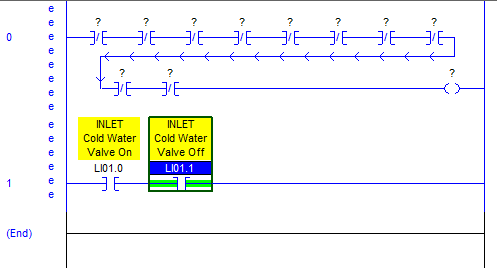
Now we can get down to business creating fault logic. During the “first pass” it’s a good idea to look through all your I/O and for each input or output ask yourself, “how would I know if the device hooked up to this input or output isn’t functioning correctly?” For instance, our first two inputs (LI01.0 and LI01.1) are “INLET Cold Water Valve On” and “INLET Cold Water Valve Off” respectively. This is a two position valve with two inputs to tell us the position of the valve. Since we have two inputs, we have an obvious consistency check we can do: we should either have one input or the other input on at a time, but never both, and the only time they should both be off is for a very short duration while the valve is changing between the on and off positions.
In our Fa_Critical routine, press Control-R to add a new rung:
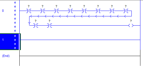
Now let’s add the condition for when both of the inputs are on. Find the “normally open” contact on the toolbar above the editing window:

Click it twice to add two normally open contacts:
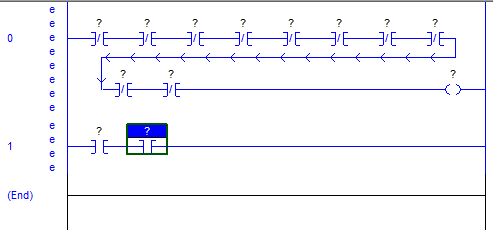
Click on the question mark above the first contact and type LI01.0 and then press enter. Then click on the question mark above the second contact and type LI01.1 and press enter. Since you already entered descriptions for these bits when you created the I/O mapping, the descriptions will show up above the contacts if it recognizes the tag:
That covers the first fault condition, when both inputs are on, but we also need to cover the condition when both inputs are off. We could add this condition on a separate fault, but I’m not going to get that fancy. But this means we need to add this second condition as a parallel branch. With the rung header selected (in the left margin where you see the number 1), click the branch icon in the toolbar:

That will give you a rather funny looking branch-around-nothing at the beginning of your rung:
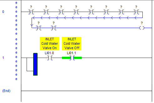
Notice that the right hand side of the branch is highlighted. In order to get the branch to go around the two contacts you just created, click down on the highlighted side of the branch and drag it over to the right side of the two contacts. As soon as you start to drag, small gray rectangles will show up between and around the contacts, and these indicate valid places where you can attach your branch. When you drag it over near the small rectangle on the right side of the contacts, the rectangle will turn into a green oval:
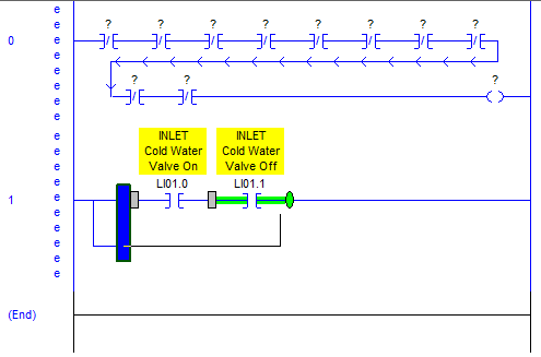
That green oval means you’re close enough to let go of the mouse button and it will attach the branch to that spot. Go ahead and release the mouse button:
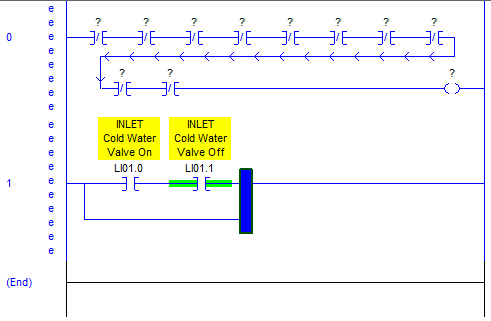
Now we want to insert two “normally closed” contacts, but if we did that with the right side of the branch highlighted, they would be inserted to the right of the branch. That’s not what we want. We want them inserted in the branch itself. First, click on the bottom left corner of the branch. It will highlight the corner like this:
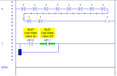
Now find the “normally closed” contact on the toolbar and click it twice:

That will give you two new normally closed contacts on the branch:
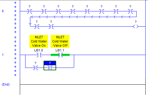
Now select the question mark above the first normally closed contact and type LI01.0 and press enter, and then select the question mark above the second normally closed contact and type LI01.1 and press enter. You now have a completed branch:
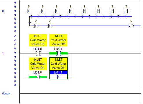
Now when these conditions are true, we want to turn on our fault, but only after a short time delay (because we want to ignore the case where the valve is actually changing states). Therefore we need a timer. Start by selecting the right side of the branch:
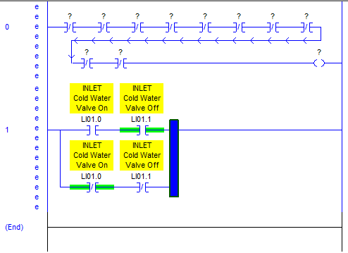
Then we need to insert an “on delay timer”. The code for this timer is “TON” (tee-on). In the toolbar, you have to select the “Timer/Counter” tab, and then you can find the TON instruction icon:

Click the TON icon and you’ll see a new timer instruction inserted on the right side of your rung:
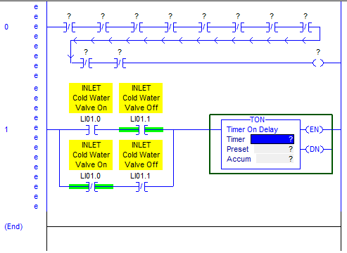
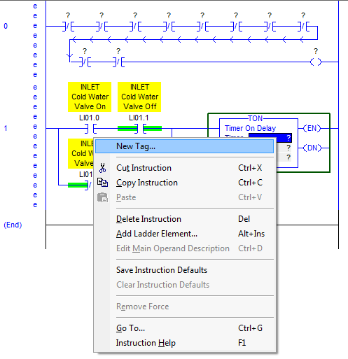
We’re going to need to create a new tag for this timer. In fact, we should create an array of tags for fault timers like I mentioned earlier. Start by right clicking on the question mark next to the word “Timer” in the new TON instruction, and click New Tag… from the context menu:
That will display a New Tag window. Let’s call the new array tag FC_TMR (meaning Faults – Critical – Timers). Put that in the name field. Enter “CRITICAL FAULT Timers” in the Description field. Now this tutorial is using a rather small example and I think we can get away with just 31 faults (bits 1 to 31 in a DINT tag), so let’s make this timer tag an array of length 32 (which will be indexes 0 to 31). Then we can use FC_TMR[1] for fault 1, FC_TMR[2] for fault 2, etc. To setup an array tag, change the Data Type field from TIMER to TIMER[32]:
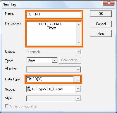
Click OK when you’re done. That created a new array tag, but it inserted just the name of the array into Timer field of the instruction:
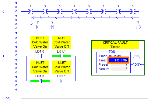
We need to tell it to use timer number 1 from the array. Select where it says FC_TMR and type FC_TMR[1] and press enter:
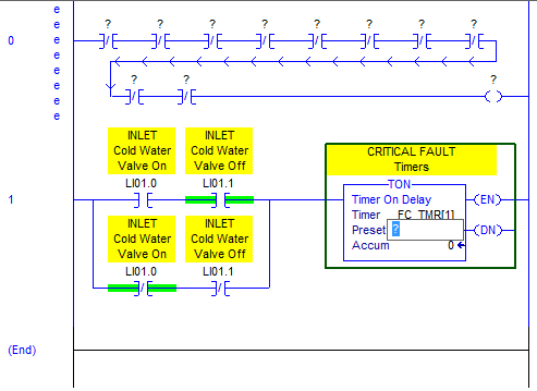
That corrected the Timer field, and it conveniently moved us to the Preset field. The Preset is the number of milliseconds that the timer will time before it turns on the DN (done) bit. In our case, enter 250 and press enter (that advances us to the Accumulator – just leave it at zero and press enter again):
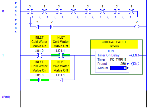
Great. You’ll notice that since this is now a completely valid rung, the “e”‘s on the left have disappeared. Now we need to create our fault bit coil. When our fault conditions are true they start the timer and when the timer runs for 250 ms it will turn on the done bit (FC_TMR[1].DN). Use “Control-R” to create another rung, and then use the “normally open” and “coil” instruction icons in the toolbar to create a contact and a coil (remember you have to go back to the Favorites tab of the toolbar instead of the Timer/Counter tab):

You should have this:
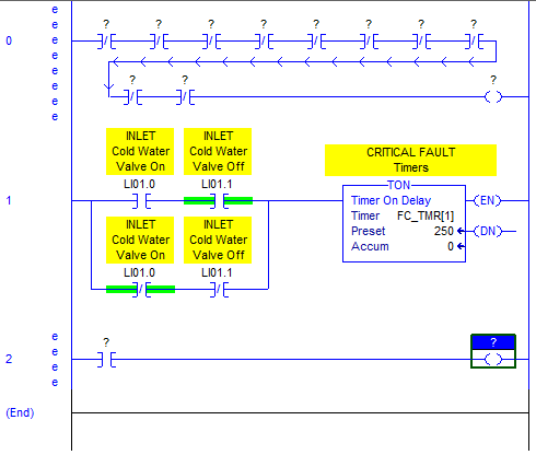
Now select the question mark above the contact and type FC_TMR[1].DN:
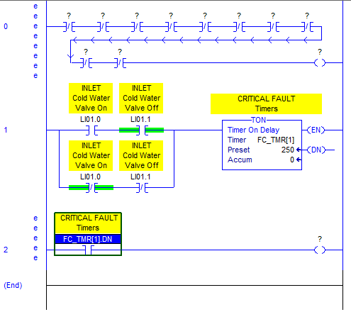
Now for our fault bit. We’ll need a new tag to store the fault bit, and as I mentioned it’s a good idea to put them in DINT tags because it’s more efficient when you’re mapping those to some kind of user interface later (communications with DINT tags seems more efficient than reading one BOOL tag at a time). Right click on the question mark above the coil and click New Tag…:
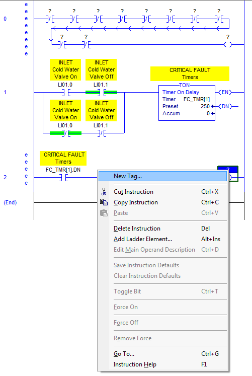
That will pop up the New Tag dialog box. Let’s give our tag the name “FC” (Faults – Critical). Enter a Description: “CRITICAL FAULTS”. Then change the Data Type from BOOL to DINT:
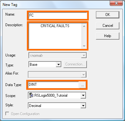
Click OK. This creates the same issue we had with the timer array above – it inserted the new DINT tag as if it was a BOOL in the coil:
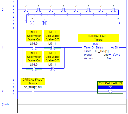
The coil needs a BOOL. Select where it says FC above the coil, then type FC.1 and press enter:
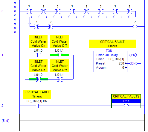
At least that got rid of the “e”‘s along the left side, so it’s a valid rung now. However, there’s still more work to be done. First of all, FC.1 needs a description (without one it just defaults to the description of the parent tag). To add a description for this particular fault, with the FC.1 text selected, press “Control-D”. That will open a description editor just above the logic window. Enter the description shown for the FC.1 coil:

To exit the description editor, either click the green checkmark, or click anywhere down in the ladder logic again.
Looking at our logic again, there’s a problem. When the condition that causes the fault is true for 250 ms it will turn on our fault bit, but as soon as the condition isn’t true anymore the fault will go away. There are a few cases where this is OK, but normally when a fault happens, we want the fault condition to “seal in” until the fault is reset. This prevents the machine from restarting until someone verifies that it’s OK. It also makes sure that an intermittent fault doesn’t keep stopping and starting the machine. In some cases stopping the machine can make a fault go away.
To “seal in” the FC.1 coil we need to create a branch around the FC_TMR[1].DN contact. You already know how to do this from above, so I won’t repeat it. Create a branch around the timer done bit, and then add a new normally open contact to that branch:
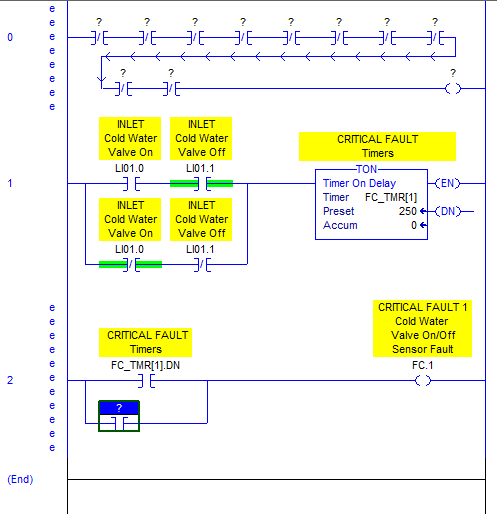
“Sealing in” means we’re going to use the coil itself as the condition in the branch. Here’s a shortcut to copy the name of the coil to the contact. Select where it says FC.1 above the coil then click and drag it over to the new contact:
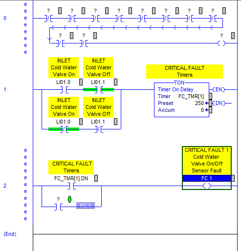
You’ll know when you’re close enough because the green oval will show up next to the contact. Release the mouse button to drop:
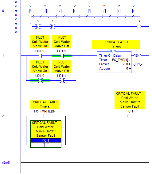
There you go! Our first fully functional fault is done. Ok, but we’ve just created a fault that can never go away once it’s been tripped right? Once it’s sealed in, nothing can ever break the circuit, so it stays on forever. Normally we would put a normally closed contact in the branch as well with a fault reset signal of some kind that would let the operator reset the fault condition after they had checked to make sure the machine was OK. This is a washing machine though, and we don’t have a fault reset button. How do you reset the fault then? I’m taking advantage of a feature of the OTE (Coil) instruction in PLCs: whenever power is removed and then turned back on, the program does a “pre-scan” that sets the state of all Coils to “off”. Therefore if this washing machine faults, it stays faulted until the owner pulls the plug out for a few seconds and plugs it back in. It may not be the most user-friendly design, but without an operator interface or a fault reset button, it works…
So, one more step: let’s hook the new fault into our summary rung. Use the click-drag method to copy the FC.1 coil name up to the first normally closed contact in the summary rung. We might as well use FC.0 as the “No Faults” coil in the summary rung too:
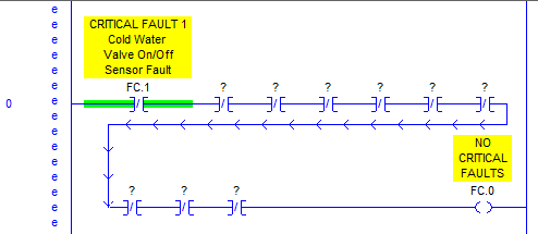
Notice that I also added a Description to FC.0: “NO CRITICAL FAULTS”.
So, that’s fault #1 done! Go ahead and finish going through all of your inputs and outputs and creating faults that cover all of them. At the end of the tutorial I’ll provide an example of the completed program for you to compare against. In the next tutorial section we’ll be using the fault summary bit (FC.0) in our rungs that control the actual outputs.
Superb!
This post made me think of superreadability in case of someone doesn’t have comments on his intervention laptop for whatever reasons… we can just make aliases from important tags to dummy tags with symbolic names, such as z_Valve_x_Fault_OnOff 🙂
I would just like to note:
You cannot simply type the Contact’s tags and have a description automatically appear UNLESS you make the input tags from Routine LI01 **CONTROLLER** tags. Because you created the tags in the MapInputs section, they are program tags, which only appear in that section of logic.
@cyureus: Actually, if you go about half-way down the page on mapping your inputs, you can clearly see that I created the LI01 tag at Controller Scope. Mapped I/O tags are typically (but don’t have to be) controller scope.
Pingback: Writing alarms and interlocks in PLC programs
The green colour under some of the contacts like ‘inlet cold water valve off valve’ means what? I assumed the coil is set at an energized state. Is that so? Real life stuff is definately different from book material we are taught in school coz at this points the books have so many NO and NC contacts while in this tutorial its almost purely NO contacts being used. If my assumption is true, does it mean every time an input like LI01.1 changes, the NO turns into NC and the already energized output relay for (INLET COLD WATER VALVE OFF) turns off. I think i am missing a basic concept somewhere. Any help?
@william – if you’re learning about this stuff in school then you’re luckier than I was. 🙂 Yes, in the case of the green highlight around each contact, that indicates if that contact is making a “completed circuit”. In the case of a NO contact, it means the referenced bit/coil is on, and in the case of a NC contact, it means the referenced coil is off. However, the NO contact doesn’t actually change to a NC contact when the coil changes state. If it’s “normally open” that means the circuit is incomplete when the coil is off (normal state). This is all based on electrical relays, so if you’ve worked a lot with relays then this would be second nature. If not, I can see where it might be confusing.
@Scott. You are right i haven’t worked with electrical relays before. What i don’t get about this is the transition of the NO and NC contacts in this examples. I expect that the contacts will flip flop on their states ones the input signal they represent comes on of off. Such that a NO contact would change to NC on signal application. For instance in the example above, what is really happening to LI01.0 and LI01.1? My biggest issue is with the background shading. If i toggle an NO contact it gets a green highlight in my program. Is this to say that it the NO0 now will act as a wire to the contacts or relay that follows it? Why not just use a NC contact and have it toggled by an input signal? This tutorial makes me appreciate real life practice.
@william – again it comes down to history. Real electrical diagrams don’t update in real time, so an NO or NC contact is always an NO or NC contact, and represents different physical paths within the device. So what changes is the coil’s “state”, and the state is represented by green or not green. However, the green doesn’t mean the coil is on or off, it means the contact is on or off. A normally closed contact is “on” if the coil is off. Therefore if you see all green across your rung, then the circuit is complete and your output instruction will be executed.
Hi, I am trying to create the contact LI01.0 and LI01.1, but the description won’t show up as you suggested. I have been following this tutorial so far, but I can’t this part to work. What I’m missing? Thank you.
I’m not sure if this was available in the version you did this in, but if you’re creating a system with FactoryTalk View SE, it’s really helpful to use Rockwell’s ALMD and ALMA instructions. These have built-in timers as well as a plethora of options, but the biggest advantage is that FactoryTalk View SE can actually subscribe to those alarms directly. Whatever you type in as the message in the ALM instruction will pop up in the FT Alarm and Event server, plus the built-in faceplates integrate directly with the instructions. Doing it this way with that HMI system will mean you will have to set up all of your alarms manually in FTView.
Pingback: Escrevendo alarmes em programas de PLC | Renato Reis
I was just wondering why you did not use a latched output in Rung 2 so FC.1 could not change. What is the advantages of doing it the way you did?
@Chris C. – I explain a little later on the page that this washing machine has no fault reset button, so there’s no way to clear the fault. However, the difference between a sealed-in coil (like I created in rung 2) and a latch is that if you powered off the PLC and powered it back up again, the PLC performs a pre-scan that will set all coils (aka OTE instructions) to off, but it won’t touch latches. That’s a subtle difference between a normal coil and a latch that I’m trying to teach here. Coils revert to off after a power outage but latches are a more permanent form of memory that retain their state. So in our case, I want the fault to reset if you unplug the machine and plug it back in.
Scott,
Thanks for your quick response. I was unaware that latched coils were not reset on start up. Thanks for this clarification.
Hi Scott, I’m using your tutorial to set up my first PLC program. However I’m having trouble selecting my mapped inputs when writing my fault logic, it looks like I have them created as program tags instead of controller tags. Can I change them or how do I select them.
Any help would be greatly appreciated.
@PadraicG – RSLogix 5000 defaults to creating a program tag, but you can choose (in the Create Tag dialog box) to create a Controller Tag instead. Once you do this, it should default to creating Controller tags all the time. There is no way that I’m aware of to change the Program Tags into Controller tags except to Cut them (CTRL-X) from the Program Tags list and paste them (CTRL-V) into the Controller Tags editor. If that won’t work you’ll have to re-create them manually.
Great work Scott. Pleased to see you stress “Readability” to your readers. (User friendly to maintenance staff who will have to use to troubleshoot equipment for its life cycle.) This exercise of yours conforms to the Best Practices of http://plc-training.org Thanks
I was wondering where I could find the completed project link, because the final part of the tutorial is no longer hyperlinked. Any help would be appreciated. I wanted to look at the completed project link to check if these are all sensor faults, or should there be other faults programmed in?
Thank you in advance,
Dalal
@DalalMuqatash – The completed file wasn’t available for download. There is only the tutorial.
I was referring to the end of this portion “At the end of the tutorial I’ll provide an example of the completed program for you to compare against.”
Where can I find the example of the complete program?
Sorry for the confusion.
Hello Mr. Scott:
You have done a beautiful job. I am amazed at your work and the little details you have provided for everything possible. Really appreciate your coursework and explanations.
thank you for the good recture you have provided to us, but have one problem, dont know the diffrent btn program tags and controller tag.
please help on ths
@christianngonyani – Controller tags are accessible from any program in your PLC and Program tags are only accessible from the program you declare them in. It’s similar to the difference between local variables and global variables.