This is part of an RSLogix 5000 Tutorial.
Normally when you’re creating a new project, you’ll be starting from an electrical design. I didn’t bother creating one for this tutorial, but assume we’re dealing with the following:
- One 16 Point Input Card (1756-IB16)
- One 16 Point Output Card (1756-OB16I)
- One Motion Control Card (1756-M02AE)
Before we add them, realize that we need to give each one a name. Naming of devices and I/O is a Big Deal ™ in the design of a control system. Consistency is important. Specifically, it’s important that it’s easy to identify the device, I/O wire, input point, and the contact or coil in the program with each other. Ideally, a person who has to look at the program later just wants to find a tag name in the program that matches the wire number or device name in the real world.
I’m also a fan of short tags and long descriptions. When you’re trying to fit lots of logic on one rung without wrapping, it’s helpful to have short tag names. If you came from the SLC 500 side, you’ll appreciate the conciseness of B3:5/0. Programmers who are new to RSLogix 5000 tend to create Really_Long_Tag_Names_Just_Because_They_Can. That’s really bad practice. Come up with short forms for all the equipment and components of your system, and stick to that for tag naming. Then use descriptions to document thoroughly.
So, we typically divide I/O into Local and Distributed, and it’s common to use L and D to denote them. Since we only have Local I/O in this tutorial, let’s start our input and output tag names with L. It’s also normal to denote whether a tag is an input or an output, so we can make the input tags start with LI and the output tags start with LO. Finally, we typically want to know what slot number each I/O card is in. Since the processor will be in slot 0, let’s put the input card in slot 1 and the output card in slot 2. We’ll put the motion card in slot 3, and let’s use M to denote it as motion, rather than an I or an O. Here are the names I’ll use for the input cards:
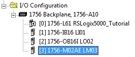
- 1756-IB16: LI01
- 1756-OB16I: LO02
- 1756-M02AE: LM03
In a later section of the tutorial, I’ll describe how to setup tags that will match these card names. That will make everything consistent. For now, if we were labeling wires in the panel, I would suggest using LI01.0 as the first input, LI01.1 as the second input, etc., and LO02.0 as the first output, etc.
Let’s start by adding the input card. Locate the I/O Configuration folder in the controller organizer window:

Since this is local I/O, it’s connected straight into the backplane of the rack. So when we add the new card, we have to add it to the backplane, not as a child of the processor. A ControlLogix system can actually support multiple processors in one rack so processors and I/O cards are peers now. Right click on the 1756 Backplane item in the tree and you’ll see an option for a “New Module…”:

Click on “New Module…”. That’s going to pop up the Select Module Dialog:
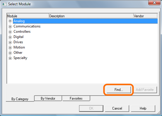
You can browse for the I/O module you want, but since we know the catalog number, just click the Find… button (highlighted above). You’ll get a simple Find Text dialog box that pops up. Enter IB16 in the text box:
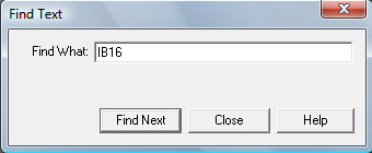
Click the Find Next button, and you’ll be back at the Select Module Dialog with the 1756-IB16 card highlighted:
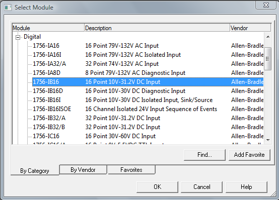
Click OK in the Select Module Dialog. For some unknown reason, it needs to know right now what the Major Revision number of the module will be (even though chances are you’re writing this program before the parts have been ordered, let alone arrived). In general, always pick the newest revision. If you’re buying new hardware for this project, chances are that’s what you’ll get. You can always change it later by deleting and re-adding the card.
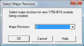
Click OK and you’ll get the New Module Dialog:
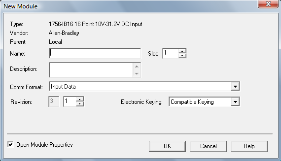
Enter the card name we chose above (LI01) into the Name field and check that the slot number is correct (it should default to 1, which is right), and click OK. You’ll now see the new module hanging off the backplane:

You’ll also see the new Module Properties Window:
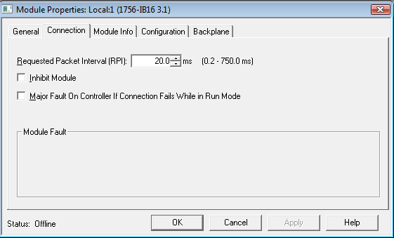
The defaults are quite reasonable for 99% of the applications I’ve seen, so just click OK to close it. Now follow exactly the same procedure to add the output card and the motion card. If you’re successful, it should look like this:
Now double click on Controller Tags near the top of the controller organizer window, and you’ll notice that by adding these cards, it has automatically created several tags that you can access to interact with these cards:

Normally we don’t interact with these tags directly (for reasons I will outline later). For now, go ahead and poke around in them to see what’s there. You’ll see that it only created tags for the input and output card. The motion card requires us to create an Axis before we see any tags. We’re going to do that in the next section of the tutorial.
hi there just wondering if ye have any book or more information on plc programming thanks
Seamus, unfortunately no, I don’t have a book. This blog has a set of articles tagged PLC: http://www.contactandcoil.com/tag/plc/
That’s about it.
The information is very usefull to me, I just want to ask if you have any networking (Ethernet,controlnet etc) information also.
Thank you for the great information provided. I have an issue , I cannot fond 1756-M02A in my catalog. I use studio 5000 mini. I added the drive using its EDS file and EDS installation wizard and now I can see the device in RSNetworks but still not in the Studio 5000. Can you help me in this ?
@MahdiarGhadiry – what you’re looking for is something called an Add-on Profile or AOP. Rockwell Automation has a page listing AOPs.
i select “I/O configuration” then right click on it but “New Module” is not active what do you think could be the reason?
thanx
Great tutorial Scott, thanks. Reply for Ahmad ‘Right click on the 1756 Backplane item in the tree’ not on I/O configuration.
Thank you for all the very nice articles.
For a CompactLogix 1769 backplane, would you consider a different naming approach? What happens if you decide to remodel a system; for instance remove a digital input card at position 3. Now all the numbering is off since the backplane doesn’t use a chassis, and everything slides over one position?
@Bruce – that’s an interesting question. I’ve never actually had that happen. You tend to add and remove single I/O points, or change the card part # (sourcing to sinking, e.g.) but by the time you get the electrical drawings the design isn’t likely to change that much. However, if it did, you can use the Edit Tag feature to just change the tag name and re-number everything. It’s not actually that much work (less time than it’ll take to update all the drawings, etc.) In your HMI you’ll have to be careful anywhere you referenced I/O tags directly but the majority of my HMI references internal coils (which I preface with “HMI_” to let later programmers beware that these tags are read and written by the HMI.
Good idea on the HMI_ tag name. I am working on a system with three 13 slot chassis of SLC500 modules, and the system used to have multiple Uticor PMD parallel interface text displays. The PMDs are gone, but the RLL files and digital output modules for communicating to the PMDs are still there. There are also some spare unused modules sprinkled into the chassis. I’m cleaning things up for the migration to CompactLogix, and will be removing the unused modules, and program files. Do you think I would be better off doing the translation first, and then making the changes in Studio 5000? Or edit/remove files in RSLogix 500 first and then translate. Thanks.
@Bruce – I’ve only done one translation from 500 -> 5000 and it went pretty smoothly without many changes. I suggest doing the translation first and doing edits in Studio 5000 because the editor is a bit nicer (and smarter about search & replace, etc.).
‘m learning a lot from your publications, congratulations!