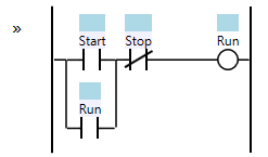
A very useful Ladder Logic Programming Pattern is the Start/Stop Circuit. This pattern is an extension to the Sealed in Coil pattern and is similar to the State Coil. However, where the State Coil is “trigger dominant” (i.e. the Trigger condition takes priority over the Break Condition), the Start/Stop Circuit is “stop dominant”:
Like the Sealed in Coil, the Run coil will always revert to a de-energized (off) state if the PLC is turned off, or if the ladder logic program is reset. That’s a useful property because when starting up the machine we likely want motors, etc., to be in the off state until the logic decides to start them.
The inputs to this circuit are the “Start” and “Stop” conditions. You could imagine both are momentary buttons on an operator screen that are on while the operator is actually pushing the button. If the operator pushes the Start button, then the Run coil will turn on, and it seals itself in until the operator pushes the Stop button. The reason that this pattern is “stop dominant” is that we want the Stop condition to take priority over the Start condition in the case where both signals are active. Imagine a case where the Start condition was stuck on for some reason. At least the operator could stop the motor, etc., by holding the Stop button on until they can turn the machine off with the main switch. Here’s an example timing diagram:

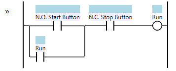
This makes more sense if you imagine that Start and Stop are physical buttons wired into inputs of the PLC. In that case we would normally wire the Start button using a “normally open” contact (so pushing the Start button turns the input on) and we would wire the Stop button using a “normally closed” contact (so pushing the Stop button turns the input off). Normally open contacts can and do get welded in the “on” position sometimes, and making the Stop button take priority over the Start button makes even more sense. In this case, the logic looks slightly different:
The reason the buttons are wired this way is so that if the wire to the Stop button becomes disconnected or power to the Stop button is lost, then the machine will act as if the Stop button has been pressed, and the motor, etc., will stop. This is presumably a safer condition than allowing the motor to continue running without the ability to stop it.
More Patterns of Ladder Logic Programming.


Something you might want to include is that if run feedback is available, that should be used in place of the run output to seal in the coil. That way, if a motor is stopped by by some condition not included as an stop condition in the logic, the run output will drop out. This prevents unexpected startup of the motor should the condition that stopped the motor clear itself, which is much safer for the maintenance folk.
@AndyJanish – That raises several important points actually. 🙂
First, let’s say the output you’re driving (i.e. the Run output) has power sourced from some kind of master control relay (MCR). Sometimes this is an e-stop MCR or a Gate Controlled MCR, depending on your machine. This is a very common scenario. In that case, you should bring that MCR signal into your PLC as an input, and then use it at the beginning of this rung so that you always turn off the Run coil if your MCR drops out. Additionally, assuming your MCR input is faster than the actual MCR dropping out, it has the convenient effect of turning off this output before the MCR contacts break, which means the MCR isn’t switching as much load. That actually makes your MCR last longer.
Next, if you go to the trouble of wiring an auxiliary contact from the Run contactor back into your PLC, you could use it as the sealed in circuit, as you suggest, or the other alternative is to add a new Fault rung, where you say, “if the Run output is on and the Feedback contact is off for more than, say 1 second, then that’s a fault.” Make sure you seal in the Fault coil. You can use the Fault coil to break the Run circuit, so you turn off the output until they press fault reset, and then of course you can use the Fault coil to drive an alarm, which is a good way to indicate to maintenance that the contactor isn’t turning on when expected (with suggestions to check fuses, the output, etc.).
Of course the Start/Stop pattern is applicable to more than just contactors and motor starters, but whenever you have a motor you typically have an overload protector. It’s definitely useful to bring the auxiliary contact off the motor overload into the PLC. Use that to create a Fault, use the Fault to break the Run rung, and also report the Fault as an alarm for diagnostics.
In the case of an automated cell, all of the Fault coils should also kick you out of auto cycle (either as an immediate stop or as a cycle stop). That prevents further operation of the cell in an unknown state.
What might you recommend for using a single Momentary N.O. Pushbutton as both the Start and the Stop actuator for the Auto-Mode process, and what risks does it potentially present?
@BrandonFarmer – I don’t like to use toggle buttons in general. When they were a physical button that stayed pushed in when it was “on” and then popped back out when you pushed it again, that at least had some tactile feedback and the contact stayed latched on. With HMIs or even lighted momentary pushbuttons, there’s too many ways that the state could be ambiguous.
There are delays in HMI systems, and we sometimes have two HMIs with the same button on both screens, and you can have interference between them (a toggle button works by reading the current state, inverting it, and writing). A physical momentary button can have debounce issues… so did the operator just push that button once, or twice, or three times?
Most people, if they want to stop a machine, want to look for a red button, and they sometimes mash it over and over again. Generally I like a button to have one meaning, or one purpose. Starting and stopping are different purposes. I don’t like to mix them.