Category Archives: Industrial Automation

Public Water Control System Attacked

Joe Weiss recently reported on the possible hacking of a public water SCADA system, apparently in Illinois. This attack, if it was an attack, caused damage to a pump by turning it on and off repeatedly.

It seems obvious that this situation is going to be repeating itself more and more. If you’re a company with industrial control systems, or you provide control system services, now’s a great time to start thinking about your control system security strategy. Do you have the necessary skills on staff? If not, where are you going to source them from?

Finding Internet-Connected Industrial Automation Devices

I think most people in our industry realize you shouldn’t connect industrial automation devices to the internet, but just in case you happen to think otherwise, here’s a quick explanation why (this is old news, by the way).

You may believe that things connected to the internet are relatively anonymous. There’s no web page linking to them, so how is Google going to find them, right?

It turns out it’s relatively easy to find devices connected to the internet, and it’s kind of like the old movie WarGames where the lead character, played by Matthew Broderick, programmed his computer to dial every phone number in a specific block (555-0001, 555-0002, etc.) and record any where a modem answered. That was called “war-dialing”. In the age of the internet, you just start connecting to common port numbers (web servers are on port 80, etc.) on one IP address at a time, and logging what you find. This is called port-scanning.

It turns out that you don’t even have to do this yourself. One free service called SHODAN does this for you, and records everything it finds at the common port numbers (web servers, FTP servers, SSH daemons, etc.) and lets you search it just like Google. It turns out that (a) most modern industrial equipment is including embedded web servers and/or FTP servers to allow remote maintenance, and (b) most web servers or FTP servers respond with some kind of unique “banner” when you connect to them, announcing who or what they are.

So, if you don’t believe that you shouldn’t be putting industrial automation equipment on the internet, here’s a little experiment you can run:

  1. Take a ControlLogix with an ENBT card and hook it directly to the internet, so it has a real IP address.
  2. Wait a couple of days.
  3. See if your IP address shows up on this SHODAN search page.

You could try the same thing with a Modicon M340.

This query for Phoenix Contact devices is particularly scary, as one of the links is a wind turbine! I was a bit scared once I opened it (it opens a publicly accessible Java applet that’s updating all the data in real-time), so I closed it. There was no password or anything required to open the page. At least the button that says “PLC Config.” appeared to be grayed out. Let’s hope that means it’s protected by some kind of password… and that it’s hardened better than every single major corporation’s website was this year.

Just want to say thanks to DigitalBond for pointing out this SHODAN search for all Advantech/Broadwin WebAccess deployments around the world too.

Control System Security Dilemmas

It’s fascinating to watch what’s unfolding in the Industrial Control System Security front these days. Digital Bond’s SCADA Security Portal is as entertaining as any (thanks to ArchestrAnaut for pointing it out for me).

A brief recap:

  • Stuxnet makes news even in the mainstream press
  • Siemens shrugs it off and does absolutely nothing about it
  • Security researchers, smelling smoke, start poking around PLC security and find it completely lacking
  • Details about wide open backdoors inserted into common PLC hardware has now been published online

Things are not moving in a positive direction either. Those security “researchers”, many of whom seem to be selling security solutions, are digging up ways to compromise PLCs and they’re posting all that information online. Now if this forces automation vendors to stop looking the other way and start taking security seriously, then I think it can only be a good move in the long term, but you have to admit it feels a little like a tire salesman throwing roofing nails on the road in front of his store.

All of this makes you wonder, what’s a small manufacturer to do? As always, businesses need to weigh the risks and the costs and act accordingly. This isn’t easy for the decision makers. On one side there’s enormous pressure to network all of the systems together to facilitate the fast flow of information between the ERP, MES, and Plant Floor layers, but on the other side, every interconnection increases the risk of catastrophic failure. I’ve personally seen Windows worms take down automation networks. In the next few years I’m certain we’re going to see worms that can jump from PLC to PLC and probably ones that can cross from Windows to PLC and back.

Properly segregating networks and then managing them is a big IT project. That means it needs scarce resources, and those resources aren’t making money for the company. Big manufacturers have enough cash flow (and have been bitten enough times) that they can allocate resources for this kind of project, but small manufacturers are a different story.

Small companies generally lack the specialists needed to implement such systems. Almost by definition, generalists serve in small companies and specialists gravitate towards large companies. Small companies can only implement commodity solutions (unless it’s part of their core business strength). That means that while we’re all worried about what might happen if a major utility or top tier manufacturer gets hit with an automation security breach, the fact is it’s more likely that small manufacturers will be the first ones hit by a fast-spreading generalized threat. The economic impact could be just as large… those small manufacturers are feeding parts up the supply chain, and in this just-in-time environment it doesn’t take much to cause a major interruption.

What’s the solution?

Short of the automation vendors waking up and making secure products, we need better (and less expensive) tools for securely connecting our PLCs. I hate to say it, but you can’t implement modern control systems without knowing the basics of network security, VLANs, and access control.

Sometimes it’s Better to Repeat Yourself

In programming, we have a principle called Don’t Repeat Yourself (DRY). It’s a very important idea, and I’d argue that most of the advances in programming environments over the years have been in support of this principle and its related principle, Once and Only Once (OAOO).

Unfortunately, like every “principle”, it eventually takes on the level of dogma, and the people spouting it sometimes forget why it exists. These principles aren’t ends in themselves; they’re not self-justified. They are general principles to follow, but only when they support the end-goal of solving problems in more efficient, and more maintainable ways.

Let me give you a very simplified example of how it can be carried to far. Consider the following declarations in C#:

const int MOTOR_1_START_TIMEOUT_MS = 5000;
const int MOTOR_2_START_TIMEOUT_MS = 5000;

Consider that I could write:

const int MOTOR_1_START_TIMEOUT_MS = 5000;
const int MOTOR_2_START_TIMEOUT_MS = MOTOR_1_START_TIMEOUT_MS;

or…

const int MASTER_MOTOR_TIMEOUT_MS = 5000;
const int MOTOR_1_START_TIMEOUT_MS = MASTER_MOTOR_TIMEOUT_MS;
const int MOTOR_2_START_TIMEOUT_MS = MASTER_MOTOR_TIMEOUT_MS;

Notice that all 3 versions accomplish the same end-result, but they are semantically different. The first version means that the two motors have independent timeout values, and they’re just co-incidentally the same. The second says, “motor 2’s timeout must be the same as motor 1’s timeout.” The third says that both motors must have the same timeout.

In my opinion, any of these three versions might be correct for various systems involving two motors. However, if you follow the DRY principle without thinking about it, you’ll assert that the first version is incorrect. In fact they’d probably say the only correct version should be:

const int MOTOR_TIMEOUT_MS = 5000;

(…ignoring, for the moment, that it should probably be a configurable value rather than a constant.)

Why does this simple example matter? Consider the case of a PLC-based control system with 10 motors. Let’s say at the start that all the motors, and all the drives running them, are identical. If you’re familiar with my philosophy of PLC programming, you know that my default solution for this would be to have 10 ladder logic routines, each called MOTOR_01, MOTOR_02, etc. Each routine would basically be a copy. That really doesn’t follow the DRY principle, does it? Certainly no, not at face value.

You might not believe it, but I get the occasional “hate mail” to my blog’s email address because of some of my technical opinions here. The most recent one, comically, referred to me (and all PLC programmers for that matter) as “dinosaurs”. I’m not sure what the rest of the message said, because if you can’t be polite, I’m not going to bother listening to you. However, I believe it’s this flagrant violation of things like the DRY principle that really rubs traditional PC programmers the wrong way when you start to talk about the principles of PLC programming.

Of course, my views about PLC programming are just that – general principles that need to be evaluated in the light of each and every project. I’m just asserting that most of the time you should be following a principle of a one-to-one mapping between ladder logic and real-world hardware. That doesn’t mean it’s an unbreakable rule.

Going back to the 10 motor example, the way you structure your program should be based on a decision you make about anticipated future changes to the system.

If you write one generic routine for controlling a motor, and you call it 10 times, you’re saying, “I always expect all 10 of these motors to behave in an identical way for all of the future.” Of course, you can allow variations, but you have to do that by passing in parameters for each instance. You have to be explicit about what can vary. Adding new parameters is typically a harder task than just modifying one of the 10 existing motor routines when you need to change the behavior of one motor.

On the other hand, if you follow my principle of 10 motor routines for 10 motors, you’re saying, “I expect that we’ll rarely need to make a sweeping change to all 10 motor control routines, but that we are likely to modify one or two routines to make them perform differently than the others.” I personally believe this is usually closer to the truth. As a system ages, perhaps one motor drive will blow, and you can’t buy the original drive anymore, so you have to replace it with a new one that has different control signals. That’s a fairly typical scenario, in my experience. Also, even though you might have 10 identical drives and motors, the process may or may not be identical for each motor. They may perform vastly different functions, and it’s likely that you’ll want to change just one or two of them to access more advanced features of the drive when you refine the process. Of course, I also like that with a one-to-one mapping in a PLC, troubleshooting becomes much easier because with online monitoring you can see each control routine executing just for that motor. You can make temporary changes just to one motor routine to bypass a faulted drive, or to do a million other changes that you’ll never be able to predict when you’re writing the logic.

The fact is, we’re physically limited by the number of drives we have. The amount of time it takes to make a change to all 10 motor control routines is tiny compared to how long it takes to make physical changes to 10 drives. This effort scales with the size of the system. In PC programming, you can have a system with millions, even billions, of objects, but in the PLC world, you’re limited by physical reality. The consequences of repeating yourself aren’t always as great, and you need to take that into account, and weigh it against your other goals.

That doesn’t mean I can’t imagine a case where you really want to assert that the motors all have to operate identically, all of the time, forever in the future. There are systems with load sharing drives where the system wouldn’t operate if you mismatched the drives or motors. That’s a design decision you have to make. Principles are only there for guidance, but they are not absolute rules, and they shouldn’t be treated that way.
Designing Database Tables for Automation People

It may seem like I’ve forgotten about this blog lately, but that’s not the case. The truth is last week I was on vacation, and before and after that I’ve been working on a project tangentially related to home automation, which I’ll probably be posting lots about in a couple of weeks.

However, today I wanted to touch on a topic that many of you will be familiar with: database design. When we talk about database design, we mean a database schema or, more generally, and entity relationship diagram (ERD).

If you do any kind of data logging, or you’re using a database as the data-store for your configuration data, you’ll have to do some kind of database design. Both of these cases call for a “normalized” design. In fact, de-normalized designs are typically only used for heavy-duty data-mining applications, so they’re pretty rare. The advantage of a normalized database is that it follows the “once and only once” (OAOO) software development principle, that says there should be one, and only one, definitive source for any particular fact. So, for instance, don’t store the operator’s name all over the place; rather, store the operator’s name in a table called Operator, include an OperatorId column that’s assigned once when the operator’s row is created but never changes, and then use the OperatorId as a foreign key in your other tables. This gives you several advantages: less database storage (an Id is typically shorter than a name), a single place to change the name (typos are always common and people change their names) and if you do have to change it, you only have to lock one database row to do the edit during the database transaction, instead of every database row that uses this person’s name.

That’s pretty standard stuff, but I want to take a slight tangent. By default, don’t store data you can calculate from other data. This is actually for the same reason. For instance, you wouldn’t store a person’s age, you’d store their birth date. That’s because the age changes all the time. I’m not saying you’d never store a calculated value, but doing so is an optimization, and “premature optimization is the root of all evil.”

Let me give you a real-life example. Lets say you wanted to record the production throughput of an automobile assembly line. Let’s assume you’re already storing the VIN numbers of each vehicle, along with some other data (various part serial numbers, etc.). I’ve seen implementations where someone’s added a new table called LineThroughput, with one row per time period, and a counter in each row (in fairness, I’ve done it too). Every time a vehicle comes off the line, the application finds the applicable row and increments the counter (or adds a new one as required). PLC programmers are particularly likely to do this because we’re used to having limited memory in the PLC, and PLCs come with built-in counter instructions that make this really easy. However, this is a subtle form of denormalization. The database already knows how many vehicles were made, because it has a record for each VIN. All you have to do is make sure that it has a datetime column for when the vehicle rolled off the line. A simple query will give you the total number of vehicles in any time period. If you follow the route of adding the LineThroughput table, you risk having a numerical discrepancy (maybe the database isn’t available when you go to increment the counter, for instance).

Just storing the datetime field has one more advantage: the database is more “immutable”. If data is only written, errors are less likely. If you do want to create a summary table later (for performance reasons because you query it a lot), then you can create it when the time period is over, and once you’ve written the record, you’ll never have to update the row. Again, this is better because the row is “immutable”. The data is supposed to be a historical record. Pretend it’s written in pen, not pencil. (You might be horrified to know that some electronic voting machines seem to use the LineThroughput table method to record your votes, which makes them extremely susceptible to vote-tampering.)

I hope that’s enough information to make my points: normalize your database, don’t record redundant information, or information you can calculate, and avoid situations where you have to update rows repeatedly, particularly if you’re doing data logging.

RAB Telecom Canada Review

I was recently in the market for some laser-printable wire labels and I stumbled across RAB Telecom Canada. The price was right for the smaller quantity I was after, so I decided to give them a shot. I was a bit confused by some of the wording on the website, so I contacted them.

The next day I had not only an email answering my question, but a personal phone call from the president, Richard, apologizing for the confusion, promising to have the site updated promptly, and he personally had the shipment in hand and ready to go. He added, “I will pay the shipping handling and for the labels in question. Mr. Whitlock I do this because I value your possible future business.”

As promised, I recently received the labels in great condition. It’s honestly some of the best customer service I’ve ever received from any vendor. It was so out-of-the-ordinary and unexpected that it shocked me. If you happen to be reading this because you typed RAB Telecom Canada into Google and arrived here, then let me assure you they exceeded my expectations.

The Role of the Engineer

John’s comment on a previous blog post got me thinking about the role of engineers in our society.

Primarily we optimize. Don’t get me wrong, there are lots of engineers that are innovators, inventors, and entrepreneurs, but I believe we’re stepping out of the core role of an engineer when we do that. Our core competency is to get more output from less input.

We’re flexible in our optimization. If we need to get a product to market fast, we can reduce the development time at the expense of resources or quality. Likewise, we relentlessly try to drive down the cost, as profit is the motivating factor behind the businesses that employ us. We do all of this within physical and legal constraints, like the laws of physics and building codes.

That’s why I think it’s funny when anyone proposes that we can “engineer” our way out of some environmental crisis. Engineers will only solve environmental problems if the environmental parameters are included in the equation. If you raise the price of oil, we’ll redesign our processes to use less oil. If you put environmental regulations in place, we’ll redesign our products to meet that criteria.

When I say that something like climate change is a problem for lawyers and politicians, not engineers, this is what I mean. It’s not a technological challenge. It’s a societal challenge. If you really want to consume less fossil fuels then replace income taxes with a fossil fuel tax and see what happens: we’ll automatically shift to other sources of energy, for we are the instruments of that policy.

As engineers, we do have some say. In our role as citizens we vote. We are involved in the creation of new building codes and international standards. Even so, it’s political will that makes change. If you’re waiting for engineering to solve these big issues, don’t. Engineering will follow policy.

Functional Programming in Ladder Logic

There’s a lot of stuff that falls under the term “functional programming,” but I’m just going to focus on the “functional” part right now, meaning when you define the value of something as a function of something else.

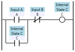
In ladder logic, we define the values of internal state (internal coils or registers) and outputs. We define these as functions of the inputs and internal state. We call each function a “rung”, and one rung might look like this:

Ladder diagram of Inputs A and B, and Internal State C

There’s something slightly odd going on in that rung though. You might say that we’ve defined C recursively, because C is a function of A, B, and itself. We all know, of course, that the PLC has no problem executing this code, and it executes as you would expect. That’s because the C on the right is not the same as the C on the left. The C on the right is the next state of C and the C on the left is the previous state of C.

Each time we scan, we redefine the value of C. That means C is an infinite time-series of true/false values. Huh?

Ok, imagine an array of true/false (boolean) values called “C”. The lower bound on the array index is zero, but the upper bound is infinite. C[0] is false (the value when we start the program). Then we start scan number 1, and we get to the rung above, and the PLC is really solving for is this:

Ladder logic defining C[1] as a function of A, B, and C[0]

If that were actually true (if it had an infinite array to store each coil’s value), then the ladder logic would be a truly functional programming language. But it’s not. Consider this:

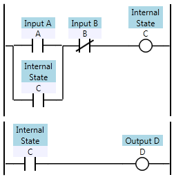
Two ladder logic rungs with inputs A and B, internal coil C, and output D

In all modern PLCs, the first rung overwrites the value of C, so the second rung effectively uses the newly computed value for C when evaluating D. That means D[1] is defined as being equal to C[1] (the current state value of C). Why is this weird? Consider this:

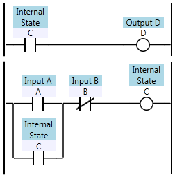
Two previous rungs with the rung order reversed

By reversing the order of the rungs, I’ve changed the definition of D. After the re-ordering, D is now defined as C[0] (the previous state value of C) rather than C[1]. This isn’t a trivial difference. In an older PLC your scan time can be in the hundreds of milliseconds, so the D output can react noticeably slower in this case.

In a truly functional language, the re-ordering either wouldn’t be allowed (you can’t define D, which depends on C, before you define C) or the compiler would be able to determine the dependencies and re-order the evaluation so that C is evaluated before D. It would likely complain if it found a circular dependency between C and D, even though a PLC wouldn’t care about circular dependencies.

There are a few of reasons why PLCs are implemented like this. First, it saves memory. We would have to double our memory requirements if we always wanted to keep the last state and the next state around at the same time. Secondly, it’s easier to understand and troubleshoot. Not only does the PLC avoid keeping around two copies of each coil, but the programmer only has to worry about one value of each coil at any given point in the program. Third, the PLC runtime implementation is much simpler. It can be (and is) compiled to a kind of assembly language that can run efficiently on single threaded CPUs, which were the only CPUs available until recently.

Of course this comes with a trade-off. Imagine, for a moment, if rung-ordering didn’t matter. If you could solve the rungs in any order, that means you could also solve the rungs in parallel. That means if you upgraded to a dual-core CPU, you could instantly cut your scan time in half. Alas, the nature of ladder logic makes it very difficult to execute rungs in parallel.

On the other hand, we can still enforce a functional programming paradigm in our ladder logic programs if we follow these rules:

  • Never define a coil more than once in your program.
  • Don’t use a contact until after the rung where the associated coil has been defined.

That means there should only be one destructive write to any single memory location in your program. (It’s acceptable to use Set/Reset or a group of Move instructions that write to the same memory location as long as they’re on the same or adjacent rungs).

It also means that if coil C is defined on rung 5, then rungs 1 through 4 shouldn’t contain any contacts of coil C. This is the harder rule to follow. If you find you want to reference a coil before it’s defined, ask yourself if your logic couldn’t be re-organized to make it flow better.

Remember, someone trying to solve a problem in a PLC program starts at an output and uses cross references to move back through the program trying to understand it. Cross referencing from a contact to a coil that moves you forward in the program doesn’t require any logical leaps, but cross referencing to a coil later in the program means you need to logically think one scan backwards in time.

Benefits

While ladder logic isn’t a truly functional language, you can write ladder logic programs in the functional programming paradigm. If you do, you’ll find that your outputs react faster, and your programs are easier to understand and troubleshoot.

How to Read Industrial Control System Wiring Diagrams

I write a lot about the PLC side of industrial automation, but it’s also fundamental to have a good foundation in the electrical side of things.

First of all, most modern (North American) industrial control system wiring diagrams have a relatively common numbering scheme, and once you understand the scheme, it makes it fairly easy to navigate the wiring diagram (commonly called a “print set”).

Let’s start with the page and line numbering. Most multi-page wiring diagrams use a two digit page number (page 1 is “01”). In the rare, but possible, event that you end up with over 99 pages, some diagrams will just add 3 digit page numbers (starting at “100”), but if there was any forethought, many designers will divide their wiring diagrams into sections, giving each section a letter (let’s say “A” for the header material, “B” for power distribution, “C” for safety circuits, etc.). Within each section, you can re-start the page numbering at “01”. This has the added bonus of letting you insert more pages into one section without messing up the page numbering.

Within a page, you’ll typically see line numbers down the left side (and frequently continuing down the middle if you don’t need the whole width of the page for your circuits). These numbers will start with the two digit page number, followed by a two digit line number. Typically these start at zero, and increment by twos:

  • 1000
  • 1002
  • 1004
  • 1006
  • … and so on

Now, devices (like pushbuttons, power supplies, etc.) usually have a device ID based on the four digit line number where they are shown in the wiring diagram, possibly with a prefix or suffix noting the device type. So, if you have a pushbutton on line 2040, the device ID might be PB2040 or 2040PB. The device ID should also be attached to the device itself, normally with an indelible etched label (lamacoid). Therefore, if you find a device in the field, you should be able to find its location in the wiring diagram. (Finding the wiring diagram, of course, is often the more difficult task.)

Wires are numbered similarly. The wire number is typically based on the four digit line number where the wire starts, plus one extra digit or letter in case you have more than one wire number starting on the same line. So, the wire numbers for 2 wires starting on line 1004 might be 10041 and 10042.

It’s typical for wires to connect to devices that are on other pages (it’s extremely common, in fact). In that case, you’ll see off-page connectors. The shape of these vary based on whose standard was used for the wiring diagram, but they’re typically rectangles or hexagons. In either case, inside the shape will be the four digit line reference number where the wire continues. The other end of the off-page connector (on the other page) also has an off-page connector in the opposite direction. Note that you frequently see connectors from one place on a page to another place on the same page, if it happens to improve readability.

That’s all you really need to know to find devices and follow wires in a wiring diagram. Now, to understand the components in an industrial control system, that’s going to take longer than a blog post. For a great introduction, I recommend the book Industrial Motor Control by Stephen Herman. Google books has a great preview if you want to check it out.