Category Archives: Industrial Automation

Introduction to Coordinated Motion Control

Let’s assume you already know everything there is to know about motion control… you can jog a servo axis, home it, make it move to a position using trapezoidal or s-curve motion. Now what?

Sooner or later you’re going to find yourself with 2 or more axes and you’re going to want to do something fancy with them. Maybe you have an X/Y table and you want it to move on a perfect 45 degree angle, or you need it to follow a curved, but precise, path in the X/Y plane. Now you need coordinated motion.

Coordinated motion controllers are actually quite common. Every 3, 4, or 5 axis mill uses coordinated motion, every robot controller, and even those little RepRap 3D printers. What you may not know is that most integrated motion solutions you might encounter in the PLC world also offer coordinated motion (a.k.a. interpolated motion) control. If you’re from the Allen-Bradley world, the ControlLogix/CompactLogix line of PLCs allows you to use the Motion Coordinated Linear Move (MCLM) and Motion Coordinated Circular Move (MCCM) instructions along with a few others. If you’re from the Beckhoff world, you can purchase a license for their NC I product which offers a full G-code interpreter, which is the language milling machines and 3D printers speak.

Under the hood, a coordinated motion control solution offers several features necessary for a workable multi-axis solution. The first is a path planner, the second is synchronization.

The job of the path planner is fairly complex. If you say that you need to move your X/Y table from point 5,2 to point 8,3 then it needs to take the maximum motion parameters of both axes into account to make sure that neither axis exceeds it’s torque, velocity or acceleration/deceleration limits, and typically it will limit the “velocity vector” as well, meaning the actual speed of the point you’re moving in the X/Y plane. Furthermore, it must create a motion profile for each axis that, when combined, cause the tooling to move in a straight line between those points. After all, you may be trying to move a cutting tool along a precise path and you need to cut a straight line. To make matters far more complicated, after the motion is already in progress, if the controller receives another command (for instance to move to point 10,5 after the initial move to 8/3) then it will “blend” the first move into the second, depending on rules you give it.

For instance, let’s say you start at 0,0, then issue a move to 10,0 but then immediately issue a second move to 10,10. You have to option of specifying how that motion will move through the 10,0 point. If you issue a “fine” move then the X axis has to decelerate to a stop completely before the Y axis starts its motion. However, you can also tell it that you only care that you get within 1 unit of the point, in which case the Y axis will start moving as soon as you get to point 9,0 and will do a curved move through point 10,1 on its way to 10,10 without ever moving though point 10,0. This is actually useful if you’re more concerned with speed than accuracy. Another option you have is to issue a linear move to 9,0 followed by a circular move to 10,1 (with center at 9,1) followed by a linear move to 10,10. That will cause the tooling to follow a similar path, but in this case you’re in precise control of the curved path that it takes. In neither case will either axis stop until it gets to the final point.

The other important feature of coordinated motion is synchronization of the axes. Typically the controller delegates lower level control of the axes to traditional axis controllers, and the coordinated motion controller just feeds the motion profiles to each axis. However, it’s imperative that each axis starts its motion at precisely the same time, or the path won’t be correct in the multi-dimensional space. That requires some kind of clock synchronization, and that’s the reason why you see options for things like Coordinated System Time Masters on ControlLogix and CompactLogix processors.

That was very brief, but I hope it was informative. If you do have to tackle coordinated motion on your next project, definitely allocate some time for reading your manufacturer’s literature on the subject because it’s a fairly steep learning curve, but clearly necessary if your project demands it.
Where to Draw the Line(s)?

One of the most confusing things that new programmers face is how to break down their program into smaller pieces. Sometimes we call this architecture, but I’m not sure that gives the right feel to the process. Maybe it’s more like collecting insects…

Imagine you’re looking at your ladder logic program under a microscope, and you pick out two rungs of logic at random. Now ask yourself, in the collection of rungs that is your program, do these two rungs belong close together, or further apart? How do you make that decision? Obviously we don’t just put rungs that look the same next to each other, like we would if we were entomologists, but there’s clearly some measure of what belongs together, and what doesn’t.

Somehow this is related to the concept of Cohesion from computer science. Cohesion is this nebulous measure of how well the things inside of a single software “module” fit together. That, of course, makes you wonder how they defined a software module…

There are many different ways of structuring your ladder logic. One obvious restriction is order of execution. Sometimes you must execute one rung before another rung for your program to operate correctly, and that puts a one-way restriction on the location of these two rungs, but they could still be located a long way away.

Another obvious method of grouping rungs is by the physical concept of the machine. For instance, all the rungs for starting and stopping a motor, detecting a fault with that motor (failure to start), and summarizing the condition of that motor are typically together in one module (or file/program/function block/whatever).

Still we sometimes break that rule. We might, for instance, have the motor-failed-to-start-fault in the motor program, but likely want to map this fault to an alarm on the HMI, and that alarm will be driven in some rung under the HMI alarms program, potentially a long way away from the motor program. Why did we draw the line there? Why not put the alarm definition right beside the fault definition that drives it? In most cases it’s because the alarms, by necessity, are addressed by a number (or a bit position in a bit array) and we have to make sure we don’t double-allocate an alarm number. That’s why we put all the alarms in one file in numerical order, so we can see which numbers we’ve already used, and also so that when alarm # 153 comes up on the HMI, we can quickly find that alarm bit in the PLC by scrolling down to rung 153 (if we planned it right) in that alarms program.

I just want to point out that this is only a restriction of the HMI (and communication) technology. We group alarms into bit arrays for faster communication, but with PC-based control systems we’re nearing the day when we can just configure alarms without a numbering scheme. If you could configure your HMI software to alarm when any given tag in the PLC turned on, you wouldn’t even need an alarms file, let alone the necessity of separating the alarms from the fault logic.

Within a program, how should we order our rungs? Assuming you satisfied the execution order requirement I talked about above, I usually fall back on three rules of thumb: (1) tell a story, (2) keep things that change together grouped together, and (3) separate the “why” from the “how”.

What I mean by “tell a story” is that the rungs should be organized into a coherent thought process. The reader should be able to understand what you were thinking. First we calculate the whozit #1, then the whozit #2, then the whozit #3, and then we average the 3. That’s better than mixing the summing/averaging with the calculating of individual whozits.

Point #2 (keep things that change together grouped together) is a pragmatic rule. In general it would be nice if your code was structured in a way that you only had to make changes in one place, but as we know, that’s not always the case. If you do have a situation where changing one piece of logic means you likely have to change another piece of logic, consider putting those two rungs together, as close as you can manage.

Finally, “separate the why from the how”. Sometimes the “how” is as simple as turning on an output, and in that case this rule doesn’t apply, but sometimes you run across complicated logic just to, say, send a message to another controller, or search for something in an array based on a loop (yikes). In that case, try to remove the complexity of the “how” away from the upper level flow of the “why”. Don’t interrupt the story with gory details, just put that into an appendix. Either stuff that “how” code in the bottom of the same program, or, better yet, move it into its own program or function block.

None of these are hard and fast rules, but they are generally accepted ways of managing the complexity of your program. You have to draw those lines somewhere, so give a little thought to it at first, and save your reader a boatload of confusion.

The TwinCAT 3.1 Review

Earlier this year I reviewed TwinCAT 3 and I admit that it was a less than stellar review. Up to now TwinCAT 3 has seemed like a beta all the way.

Well, I’m pleased to say that after using and deploying TwinCAT 3.1 for several weeks, it’s a significant improvement over its predecessor, and brings it into the realm of “release-quality” software. There are several improvements I’ll try to highlight.

64-bit! Finally! Yes, it’s so nice to get rid of the old 32-bit copy of Windows 7 and get back to the world of 64-bit computing.

The TwinSAFE safety editor is so much better. While the old one would take several minutes to verify my safety program before downloading it, and several minutes to even get online with the safety controller, this new version does it in seconds. It was so fast in comparison that I thought it didn’t work the first time. Thank goodness because that was a major shortcoming of the old version.

I’m pleased to report that Beckhoff has made changes to the source code file format to make them more friendly to source control applications (like Subversion or Mercurial). Doing a “diff” between 2 file versions now gives you a really good idea of what changed, rather than some obscure XML code. This is one of the first things I complained about and I didn’t expect it to get changed, so I’m really happy to see that. (Also remember that TwinCAT 2 files were completely unfriendly to Source Control; they were just a big binary blob!) Note that when you upgrade your TwinCAT 3.0 solution to TwinCAT 3.1, it has to do a conversion, and it’s one-way. Keep a backup of your old version just in case. In our case, the upgrade went well, except for references, but that was ok…

The old library manager in each PLC project has been replaced by a References folder, which you will be familiar with if you do any sort of .NET programming. You can now add and remove library references right in the solution tree, which is nice. That’s one thing that didn’t get upgraded automatically. I had to remove my old references to the TwinCAT 3.0 standard libraries and re-add them as TwinCAT 3.1 libraries. Not a big deal once I figured out what was causing the build error.

The scope viewer has been removed from the system tray icon menu and pulled into the Visual Studio interface. I think this is just part of their attempt to pull everything into one environment, which I applaud.

Unfortunately I still had one blue-screen-of-death when I tried to do an online change, but I couldn’t reproduce that problem. I’m using a commercial desktop computer, not an industrial PC for my testing, and Beckhoff says they won’t support the software if it isn’t installed on Beckhoff hardware. Let that be a warning to you: even though you pay significantly more for the software license in order to run it on non-Beckhoff hardware, they will not warranty software bugs in that case. That doesn’t mean you can’t get local support, but it does mean that if you have a legitimate bug report, they won’t help you unless it can be reproduced on Beckhoff hardware.

While upgrading, I also upgraded the operating system on the PC from Windows 7 32-bit to Windows 7 64-bit. That created a small problem because it caused the Beckhoff generated system ID to change, and the license is attached to the system ID. That means I have to go through generating a license file and applying the response file again. Hopefully there are no problems with duplicate licensing, as it is the same physical computer. I’m still waiting for a response though.

I did run into a couple gotchas during the upgrade. First, TwinCAT 3.1, for whatever reason, requires Intel’s Virtualization Technology Extentions (VTx) to be enabled in the BIOS, and mine weren’t. It turns out that I needed to flash the BIOS to even get that option. Secondly, we use Kaspersky Endpoint Security version 8 for our enterprise anti-virus solution. It turns out that both version 8 and version 6 prevent TwinCAT 3.1 from booting the PLC runtime into Run Mode on startup. Without Kaspersky installed it worked fine. I eventually tried Microsoft Security Essentials (the free Anti-virus solution from Microsoft) and that seems to work well. Some anti-virus is better than none, I figure.

The upgraded system has been in production for nearly 2 weeks, and seems to be working well (no problems that I can attribute directly to TwinCAT, at any rate).

In summary, if you’re looking to jump into TwinCAT 3, I know I said to wait in my last review, but I now think that TwinCAT 3.1 is a good solid base if you’re looking to get your feet wet.

Secure Design of Safety Critical Software-Controlled Devices

As a licensed P.Eng., I recently received a copy of a draft version of a document regarding engineering practices for the design of safety critical software. It seemed to be well thought out and written, but one of the last statements caught me by surprise. It basically said that your design should prevent Stuxnet-like attacks.

I think it’s great that the profession is starting to take this stuff seriously, but I was a bit shocked at the implication of this document. Primarily I was concerned because Stuxnet was nothing like an ordinary attack. Defending against it would be like defending your office building against a laser guided bomb. Stuxnet was a nation-state-backed attack with huge funding and resources, going after a military/industrial target.

What does that mean for us practicing engineering in, say, the automotive industry? Do we just get to brush the whole cybersecurity thing aside because a Stuxnet-like attack against our facility has absolutely zero chance of ever being launched? It doesn’t seem like that’s what the document was trying to say.

In fact, is Stuxnet even a relevant example for “Safety Critical Software”? Did Stuxnet actually affect any safety critical systems, like a Safety PLC? All it did was damage equipment. Was anyone hurt? Was anyone in danger of being hurt? I guess I just disagree with the use of Stuxnet as an example here.

That’s not to say cybersecurity doesn’t need some attention from our profession. In particular, consider the case of so-called “Safety PLCs”. Here you have a device, typically sitting on some kind of network, definitely responsible for safety critical systems. There are at least 2 pieces of software installed on a Safety PLC: the firmware (the operating system, communication system, and runtime of the device) and the user-configurable logic that you download when you’re programming the system. Compromise of either of these pieces of software certainly poses a grave risk to human safety.

The user-configurable logic is supposed to be password protected. This is one step up from normal PLCs which rarely offer any kind of authentication. Now, when TUV, or whoever, is certifying these devices, they are definitely checking that once it’s locked, you can’t update the user-configurable software without a password. In fact, TUV has access to the design, so I *hope* someone there is well versed in cyber security and knows what they’re talking about. For instance, if it was found that authentication was being done in the programming software (client application) and not on the device itself, it would be completely useless security, because someone could easily bypass it. But let’s assume that nobody building these things is doing anything that blatantly wrong.

So even if the client/device protocol is rock solid, is the firmware bulletproof? I think this is unlikely. Every time a security researcher runs even the most basic of security audits against PLCs they usually find tons of obvious exploits. You have to realize that most of these devices are just embedded computers running off-the-shelf real-time operating systems like VxWorks. Usually it’s using the standard VxWorks networking protocols, which are sometimes known to have vulnerabilities (in certain versions) and are unfortunately rarely updated in the field. That’s not even counting deliberate backdoors and debug code left in the software. Does TUV do a security audit of every design? Maybe, but I doubt it. Even if they do, are they doing repeated security audits against older devices? When new vulnerabilities are found in these embedded operating systems that impact existing devices, are they requiring them to be recalled? I’ve never heard of such things.

I’m pretty sure the only reason we haven’t heard about this yet is because even security researchers who’ve woken up to the concept of PLCs and SCADA systems in the past 2 years still have no idea that Safety PLCs actually exist. I don’t think it’ll be too long until they find out.

Designing a device like this that’s intrinsically secure against hacking seems almost impossible to me. Whatever software module is responsible for receiving the user-configurable safety program and storing it in the persistent memory of the device is necessarily network-facing. Any vulnerability in that communication module could be exploited, and then you have the ability to bypass all the security protocols on the device, and write whatever user-configurable safety program you want.

So if this document says we have to design our Safety Critical systems to withstand a Stuxnet-like attack, and all the Safety PLCs we could use are likely vulnerable via communication module software exploits, and even firewalls and airgaps don’t seem to be able to defend against this kind of attack (just ask the employees of the Natanz facility in Iran), then where does that leave us? Is a P.Eng. supposed to just throw up their hands and say “sorry, it can’t be done?” Not likely.

The TwinCAT 3 Review

Edit: Note that I have posted an updated TwinCAT 3 Review in 2014.

So back in 2010 I wrote about my first impression of TwinCAT 2 and later that same year I wondered if automation programmers would accept TwinCAT 3. I was lucky enough to be involved in the TwinCAT 3 beta, and now that the 32-bit version of TwinCAT 3 is available for general release we’ve deployed 2 production systems based on TwinCAT 3, and will likely deploy more in the future. What follows are my impressions of the current state of TwinCAT 3 based on our experiences with those 2 systems.

I think the best way I can describe TwinCAT 3 to the non-initiated is by comparing it with Allen-Bradley’s ControlLogix platform with their RSLogix 5000 programming environment. I say that because I’m familiar with that platform, and so are most of my North American readers (I assume). It speaks well of Allen-Bradley that they are the de-facto default control system platform around here.

We often fall back on car analogies, and I don’t want to break with tradition. If ControlLogix is the Ford Taurus of control systems (common, reliable, with lots of performance for most tasks, lots of room, and fairly maintenance free) then TwinCAT 3 is something like the Rally Fighter. That is, it’s road legal, fairly rare, requires lots of TLC and understanding and may not be as reliable, but will take you places you’ll never get to go in a Ford Taurus.

When it comes to speed, TwinCAT 3 with Beckhoff’s EtherCAT I/O is a beast. I can’t stress this enough. We’re running both production systems of TwinCAT 3 with both a 0.5 millisecond logic scan time and a 0.5 millisecond I/O bus scan time and we’re only using about 10% to 15% of the available horsepower of each system. You can see and react to things in the TwinCAT 3 system that you’ll just miss in a ControlLogix processor. For instance in one case we’re driving an output off of an absolute encoder and the repeatability of turning on that output is much better than anything we’ve seen with any other controller.

Furthermore, data accessibility is light years beyond any traditional PLC. In one test I moved a 400 kB block of data from the real-time (ladder logic program) to a .NET program running under windows on the same PC and all I can say is that it’s nearly instantaneous. That’s an advantage of having the HMI and real-time executing on the same physical hardware.

That’s not even getting into the new C++ integration (which I haven’t used).

Any TwinCAT 3 vs. ControlLogix system comparison will also certainly favor the Beckhoff solution when it comes to price. At least I can’t seen any case yet where that’s not true by a significant margin. I can’t say exact prices, obviously, but I’m confident that’s generally a true statement.

Does that mean I think the competition is a hands-down blow-out in favor of TwinCAT 3? No. In fact if you’re considering trying TwinCAT 3 I can’t even go so far as to give you my blessing right now. It has problems.

TwinCAT 3 crashes with a blue screen. Regularly. There, I said it. That’s the dirty secret. Everyone’s fears about PC-based control on the factory floor were around stability and in our experience TwinCAT 3 isn’t stable yet. This is odd to me because we have another system with TwinCAT 2 and it’s solid as a rock. Unfortunately our TwinCAT 3 system crashes with a blue screen regularly, and the crash report always shows that it’s some kind of memory violation in their Tc*.sys files, which are the system files responsible for running their real-time system under ring 0 of the OS (as far as I understand). I’ve never even seen blue screens with Windows 7 until trying out TwinCAT 3. There are actually two different times that it crashes: (1) randomly, and (2) when I try to do an online change.

Beckhoff’s response was that we were running it on 3rd party hardware. They loaned us a Beckhoff industrial PC to try. We tried it for a week and we didn’t see any random crashes, but it still crashed the real-time when I tried to do an online change, and it also crashed the IDE almost every time I recompiled the program. In fact that’s the reason we had to stop the test with Beckhoff’s hardware after only one week. I needed to compile a change and couldn’t get it to compile. It did work on our 3rd party PC (an HP desktop PC).

Now, I don’t think these are insurmountable problems. Beckhoff is still coming out with new versions on a regular basis. Their new support for 64-bit windows operating systems is on the horizon. TwinCAT 2 seems stable and I’m sure TwinCAT 3 will get there eventually. However, for the moment, if you’re considering the plunge, I suggest waiting about a year before bothering to check it out. If you just need the speed, consider TwinCAT 2, as even though it doesn’t take advantage of multiple cores it will likely do what you need and is a much more mature product at this point.

Finding Inexpensive 24VDC Power Supplies

I happen to have been in the market for some switching 24VDC power supplies that could source some decent current and put up with a little abuse. It turns out there’s no need to spend hundreds of dollars for one of the fancy DIN-rail mounted models when all you need is a box to sit on your test bench.

You can order them directly from Chinese suppliers, but it’s more convenient to order from someone domestic. I’ve found a good place to look is Amazon (a close second is E-Bay, but you’re really buying from China in about 50% of cases there). On Amazon you can get a 15A 24VDC power supply for well under $30:


Obviously this is a “buyer beware” type of situation, but I’ve purchased 3 similar power supplies so far, and haven’t had any problems. In one case the equipment under test shorted out due to a blown capacitor, and the power supply turned itself off until I cycled the power to the supply. It’s still working fine.

You may think that a $300 brand name power supply is what you need, but if you don’t need five 9’s of reliability then I’d like to point out you can buy ten of these cheap supplies for the same price, so buy 3 and keep 2 on the shelf, and spend the other $210 on other cool gadgets! 🙂

More Control Systems Found Attached to the Internet

Back in November I published a blog post about Finding Internet-Connected Industrial Automation Devices and one of the scariest things I found was a wind turbine in Oklahoma with no apparent authentication.

Recently Dan Tentler took this several steps further and posted his video from the LayerOne 2012 security conference, where he shows you a vast array of non-secure devices connected to the internet, much of which can interact physically with the real world, including control systems. Here’s his extremely fascinating video, and it’s worth watching all 45 minutes (note that he also has a screenshot of the Endurance Wind Turbine interface that I found in my original post):

The Psychology of Automation

It’s easy to overlook the power of human motivation in automation systems.

I’m going to assume you don’t work in a lights-out factory. That’s pretty rare. Almost all automation systems interact with people on a regular basis, and even though we have high fidelity control over our automation processes, people are notoriously difficult to predict, let alone control.

For instance, consider a process with a reject station. Finished parts are measured and parts that don’t meet specification are diverted down a chute. Good parts continue down the line.

Question: how big do you make the reject bin? Naively you might want to make it as big as possible so the operator doesn’t have to waste time emptying it. Unfortunately that means it’s just as easy to make bad parts as it is to make good parts. You’d be better off to make the reject chute only hold 3 parts, and put a full sensor on the chute that throws a fault and stops the machine when it’s fully. Then it’ll be a pain in the ass to make bad parts, and the operator will have a lot more motivation to do something about it. While you’re at it, put the reject chute on the other side of the machine so they have to walk around the machine to empty it.

Consider a machine with an e-stop button. It’s a big red button with a mushroom head that’s supposed to be easy to hit. However, I’ve seen a lot of machines where the consequence of hitting that button was major downtime because the part tracking got screwed up or the machine just didn’t recover gracefully. I once watched a pallet get bumped out of the track and it was riding along the rail of the conveyor. I hit the e-stop just before it was about to damage some equipment. I was scolded for my efforts: “never hit the e-stop,” he said. That’s the wrong motivation. You want operators to press the button when they see something wrong, so make it easy to recover.

Consider an inventory tracking system. You want people to record stuff they’ve consumed, and what cost account they’ve consumed it against. What motivation does a person standing there with a bolt in their hand have to look up that bolt in your inventory system and mark it consumed? Very little. What if you lock the door to the store room and make them request an item before you unlock the door? That’ll help, but chances are some people who don’t know exactly what they want will click the first item on the list, and just go in and browse. What if you make the inventory storage system so convoluted that the only way to find an item is to look up the storage location in the computer? Well, that might work (until your inventory system breaks).

Like water, people tend to take the easiest path down hill. You’re better off digging a channel where you want it to go than expecting it to get there under its own power. Use gravity to your advantage. Make it harder to do things the wrong way and easier to do things the right way.

Safe(r) Data Collection from a PLC

There’s been a lot of discussion recently about the dangers of connecting automation equipment to networks, and yet there are significant pressures to do so. Of course, I don’t ever think that you should take a PLC and put it on an internet accessible IP address, but it’s certainly common practice to connect industrial automation equipment to internal LANs to facilitate data collection. People in the front office need to push production planning information down to the production floor, and they need real-time data on what’s going on (not to mention for historical data logging, historians, etc.).

It’s all too common to throw a PLC on the same network as your front office, and I’ve seen it blow up. What happens is something invariably goes wrong on the office network (someone plugs two ports together on the switch in the boardroom, or someone brings in an infected music player and plugs it in, or the DNS server at head-office goes down and the local DNS doesn’t work correctly… I’ve seen a lot). However, you want your machines to keep going when this happens.

This is all made worse now that (a) industrial automation equipment is more commonly based on off-the-shelf commodity hardware and software (e.g. windows PCs) and (b) the people writing malware can actually spell PLC now. Up to this point there’s been some form of security through obscurity.

If you have a local IT staff that’s on the ball, you really should be getting them to handle the network layout. On the other hand, if you’re in a small facility with limited resources, there’s a lot you can do by making some simple design choices that will go a long way towards improving the reliability and security of your systems.

Most automation cells now come with an Ethernet switch already built-in. Typically this is an industrial spec. DIN-rail mounted one. It’s not fancy, but it’s supposed to survive in a panel. These Ethernet switches are there to connect your PLC to your HMI, and increasingly to connect your PLC to Ethernet-based I/O like Ethernet/IP, etc. The common (and wrong) thing to do is to drop a network cable from your plant network to your panel and plug it right into this Ethernet switch. This creates some technical problems right off the bat:

The automation devices typically have fixed IP addresses (I personally prefer this because it means these devices aren’t dependent upon an external DNS or DHCP server – two less dependencies are good). Chances are that these IP addresses won’t work on your plant network, so you have to manage those IPs at the plant level. You’re opening yourself up to someone with the wrong IP on their laptop pouncing on your PLC’s IP address, and then bam, your machine is down.

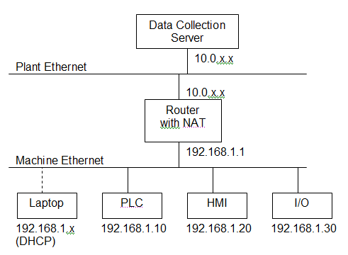
A much better way is to place some kind of Router with NAT between the plant network and the machine’s Ethernet Switch:

Now if you’re just a little manufacturer with two machines out back and your data-collection link isn’t critical, you can probably get away with one of those home routers from Best Buy that you’d use to connect your laptop and your desktop at home to your cable modem. Note that it doesn’t need to be wireless, and you’re probably better off if it isn’t. The way you hook it up is to connect the Internet (Uplink) port on the router to the plant network and run a cable from one of the ports on the LAN side to the existing Ethernet switch in the machine. If your data needs to be a bit more reliable, consider buying some kind of Cisco router with NAT capability (but you’ll be going from the $50 range to many hundreds of dollars – your choice).

Now, when you configure it, you want to make sure that you turn off the port forwarding function, the DMZ function, disallow remote administration, and block all anonymous internet traffic (these should be default settings, but it’s good to check). Also, make sure the router’s local IP address doesn’t conflict with the PLC’s and HMI’s, and make sure they have the same subnet. Typically you’ll want to either turn off DHCP on the local side, or limit it to a range that won’t conflict with the fixed IPs. DHCP is handy when you connect your laptop to the programming port. Now what you’ve done is made it somewhat invisible from the plant side. Some piece of malware scanning for devices on your plant network should just see a black hole.

Now on the PLC side, you can now initiate a connection to the data collection server even though the data collection server can’t connect to the PLC (in the same way that your home computer can connect to Google, but Google can’t get to your PC – theoretically). Note that a piece of malware on your data collection server or on one of the routers/switches in your plant network could intercept this communication, and own your PLC, but at least you’ve significantly reduced the surface area of attack. Not perfect, but reasonable at this time, depending on the sensitivity of your equipment. I’m assuming you’re not enriching uranium or providing drinking water to my community.

(I’m going to be talking specifically about Allen-Bradley products now – sorry.)

So how do you get the data from the PLC to the data collection server? In the old days you’d have some software on the server like RSSQL, and it used a product like RSLinx Enterprise and as far as I know, it initiated the connection to the PLC. That won’t work in this case. Sometimes you’d throw an OPC server in there, and have some kind of historian that would log tags to a database. That OPC server, obviously, needs to be able to initiate a connection to the PLC. To use a router with NAT, you’d need to port-forward from the router to the PLC (or to the OPC server if it was inside the machine network). That’s undoing a lot of our protection.

What you need to do is initiate the connection from the PLC, and have the Data Collection computer act as a Server. One way to do this is with a 3rd party Ethernet card, like this MVI56-GEC card from Prosoft for the ControlLogix line. I have used that in the past to connect to a server, but it involves a lot of ugly PLC coding. It’s your only option if you have to conform to someone else’s protocol though.

If you just want to write data directly into a SQL database, there are 3rd party products that will let you do this (basically a SQL Server connector card).

But there is an option without buying any new hardware. The ControlLogix/CompactLogix lines can send Unsolicited CIP messages, and you can find products that can receive these messages in the PC world, like CimQuest’s NET.LOGIX product. It can act as a server and receive data directly from the PLC – either individual tags, or even arrays of UDTs. The code on both ends is relatively simple, so all you have to pay for is the NET.LOGIX runtime license, which is cheaper than the hardware alternatives. Note that you can also do this with PLC5 and SLC500 devices, though there’s some more effort involved.

I hope that’s enlightening. This is by no means a perfect solution, but it’s reasonable for now. It doesn’t plug the laptop hole (the programming laptop is probably still your #1 vector for malware to get into your machine network). It’s susceptible to man-in-the-middle attacks between the router and the data collection server. It’s susceptible to exploitable bugs in the router’s firmware. Beware and use your own judgement.

Internet Facing Water Management Infrastructure in Texas Exploited Easily

Completing the trilogy of ICS-security related blog posts, a hacker recently demonstrated how easy it was to find and log in to an internet-facing SCADA system using for water management in a town in Texas. From the article on threatpost:

The hacker, using the handle “pr0f” took credit for a remote compromise of supervisory control and data acquisition (SCADA) systems used by South Houston, a community in Harris County, Texas. Communicating from an e-mail address tied to a Romanian domain, the hacker told Threatpost that he discovered the vulnerable system using a scanner that looks for the online fingerprints of SCADA systems. He said South Houston had an instance of the Siemens Simatic human machine interface (HMI) software that was accessible from the Internet and that was protected with an easy-to-hack, three character password.

For those of us who design, build, and deploy systems like this, let’s ask ourselves what would happen if a serious incident happened and significant equipment damage was done, or worst case, people were seriously injured or killed. Don’t you think the people who worked on the system would end up in court (if not in criminal court, then at least in civil court)?

When in doubt, don’t sit these things directly on the internet. There are lots of secure remote access products available (Google for “VPN”). It’s worth it.