I’m still working on my RSLogix 5000 Tutorial, and I decided to include a brief introduction to a Five Rung Logic Block. If you’re like me, the first time you saw or heard about a five rung, you thought it was was a ludicrous amount of logic just to move a cylinder from one position to another. However, I realized most of my non-five-rung motion control logic always ended up being as complicated, or more complicated, than if I’d used a Five Rung from the beginning, so now I’m a convert.
A five rung block is named after the five coils that make up each block (these names differ between programmers and organizations, but they follow this pattern):
- Safety
- Precondition (aka Trigger)
- Command
- Complete (aka “In Position”)
- Fault
Briefly, your safety rung contains all the conditions that must be present during the entire motion. You put conditions like “no critical faults” here. You also put conditions such as interfering axes clear here. For instance, if axis A and axis B should never advance at the same time, then put A Retracted in the safety rung for the five rung that moves axis B to the Advanced position, and vice-versa. This is your “sanity check” logic.
The “trigger”, or “precondition” rung is the signal that will initiate automatic motion. You can put auto conditions directly in this rung, or you can tie in auto mode sequence logic from elsewhere. The difference between the Safety rung and the Trigger rung is that the Safety rung has to stay on during the entire motion, but the Trigger run only has to be true to initiate the motion.
The Command rung is usually a sealed in coil that turns on while the machine should be trying to move this axis to this particular position. Sometimes this is synonymous with an output itself, but in many cases the Command coil will then be used to drive one or more outputs or motion instructions.
The In Position (sometimes called “complete”) rung condition is the logic that interprets the sensors to tell us that we’re actually in the given position. It’s handy to use this coil throughout your program to indicate the state of the machine, rather than looking at the inputs directly. That allows you to invert input logic or add debounce logic later in just one place, rather than everywhere that depends on this machine state.
Finally, the Fault condition is normally a timeout fault. If the command coil is on too long without seeing the In Position signal, then we determine that the motion timed out, and we stop trying. We use this fault in our alarm logic as well.
Once the command condition becomes true, it’s normally sealed in until one of three things happens: the safety condition changes to false, the motion completes and the In Position signal changes to true (normal), or the motion times out and the Fault condition changes to true.
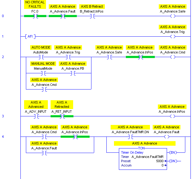
Here’s what a generic five rung logic block looks like. I left an AFI in the trigger rung because you normally come back and fill in that logic later. Note that this is only to move one axis to one position:

The “PB” bit in the command rung is the HMI pushbutton that initiates motion to this position while you’re in manual mode. Note that both manual mode motion and auto mode motion have to follow the same safety conditions, but just have different trigger conditions.
You have to customize it for each situation. The contents of the safety and trigger rungs are obviously unique, but the command rung sometimes changes depending on the scenario. You may have more than just manual and automatic modes. Some automatic actions may actually happen when you’re not in automatic mode. Sometimes you may want an axis to “jog” (for instance a hydraulic axis moves slow, and you may want it only to move in manual mode if you hold your finger on the button) and in that case, you couldn’t seal in the Command bit around the manual mode pushbutton (you’d just seal it in around the trigger contact).
There are other variations. I hope you find this useful. If nothing else, when you come across this logic in someone else’s program, you’ll have a better idea of how it works.
perfect!
Pingback: The Ladder Logic/Motion Controller Impedance Mismatch · Contact and Coil
Thanks Scot for the developing such a great and helping website, I found the problem many of my issues, your way of teaching is very good. Please also upload the lessons on Add-On Instructions, to use message instruction on emulator 5000 and also lessons on Instructions.
@couchpitt
@964-port
May 23,2020
Saturday
prof;
can we talk some more about the
logic behind contact status when
it should be n/o
when it should be n/c
appreciated
Thanks a lot, it was very helpful.