A little while ago I told you about an ongoing project to automate my parents’ G-Scale outdoor model railroad. Today I’m going to add a bit more detail about the solution: specifically, how do you sense the location of the trains?
Layout
The layout is broken into 3 lines: a “Figure 8” line, a “Point-to-Point” line, and a “Main Line”, which has various track switches, sidings, etc. The interesting thing about the Figure 8 and Point-to-Point lines is that they cross, and one of the goals is to prevent trains from colliding.
Some other goals include:
- The point-to-point should start at one station, move to the other station, stopping out of site for a while. It should stop at each end-station for an adjustable period of time, and return.
- The Point-to-Point and Figure 8 lines have uphill and downhill sections, so the speed needs to be varied in these sections.
- The Figure 8 line has two programmable stops, but the train shouldn’t necessarily stop at both stops every time.
- We want to run multiple trains on the main line. Some will be stopped on a siding while others are running, and then they will switch.
- All tracks need the ability to be manually operated.

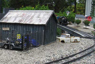
The Figure 8 Line from behind "Stan's Speed Shop"
Power
All existing locomotives in the system use “track power” (DC voltage applied across the two rails of the track). The voltage applied to the track is applied to the motors in the locomotives, and this controls the speed.
There are some advantages to this: it allows you to run “stock” (unmodified) engines, and it’s compatible if someone wants to bring over a “guest” engine (either a track powered or battery powered model). It’s also compatible with “DCC” controlled locomotives which, as I understand it, are backwards compatible with track powered systems.
Control?
Whether you use a PLC or a PC for control, being able to control the voltage to a track (to control a motor speed) is pretty much a solved problem, so let’s assume we can do that for now. The main problem is location sensing. In order to tell the locomotives to stop, wait, start, etc., you need to know where they are.
Your first thought, as a controls engineer, is some kind of proximity sensor. Unfortunately there are some significant problems with this:
- Metal-sensing proxes are expensive, and the locomotives are mostly plastic. We’re trying to avoid retrofitting all locomotives here. You might be able to sense the wheels.
- Photo-sensitive (infrared) detectors, either retro-reflective or thru-beam type, are popular on indoor layouts, but they apparently don’t work well outdoors because sunlight floods them with infrared.
- Reed switches are popular, but you need to fit all your engines with magnets, and they are a bit flaky. Magnets and reed switches actually work well if you have the magnet on the track, and the reed switch mounted to the engine, in order to trigger whistles, etc., but even then they’re not 100% reliable, in our experience.
- All proximity detection strategies require you to run two wires to every sensor, which is a lot of extra wiring. Remember, there are lots of little critters running around these layouts, and they tend to gnaw on wires. Fewer wires is better.
- Having sensors out in the layout itself means you’re exposing electrical equipment to an outdoor environment. At least you can take the locomotives in at night, but the sensors have to live out there year-long. I’m a bit concerned by that thought.
Solution: Block Occupancy Detection
The solution we found was a technique called “block occupancy detection.” This is a fairly common method of detection in some layouts. A couple of years ago, I built a simple controller that solved the crossing detection problem between the Figure 8 and Point-to-Point lines using block detection to know where the trains were. It worked great, so we decided to use it for the entire system.
Here’s how it works: you divide up your track layout into “blocks”. Blocks can be any size, but they are typically anywhere from about 4 feet long, up to the length of a train, or a bit more. One rail on the line is “common” and isn’t broken up. The other rail is the one you cut into electrically isolated sections.
So, the wire from the common side of your speed controller goes directly to the common rail, as it did before. However, you have to split the “hot” side of your speed controller into as many circuits as you have blocks. Each block is fed from a separate circuit, which means you have to run a “home run” wire from each block back to your power supply.
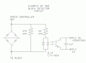
Then, the “block occupancy detection” circuit is wired in series with each block circuit (between the speed controller and the block). Here’s what one block detection circuit looks like:

This is an interesting circuit. On the left you can see a bridge rectifier, with the + and – terminals curiously shorted out. This is a hacked use of the device. All we really care about is that we want to create a voltage drop across the device when current is flowing through the wire to that block. One diode creates a voltage drop of 0.6 to 0.7 V, and the way we’ve wired it, whether the speed controller is in forward or reverse, the current always has to take a path through two forward-biased diodes. That means, when current is flowing to the block (i.e. there’s an engine in that block) then we get a voltage drop of 1.2 to 1.4 V across this device (or -1.2 to -1.4 V if it’s in reverse). A standard bridge rectifier is just a handy component to use because it’s readily available in high current ratings for a couple of dollars each.
We’re using that constant voltage to drive the input side of an LTV-824 opto-isolator chip. Notice that it’s a bi-directional opto-isolator, so it works in forward or reverse too. On the output side of the opto-isolator, we can run that directly into a PLC input (the input we’re working with here is sourcing and has a pull-up resistor built-in).
If you’re using a regular straight-DC analog controller, that’s all you need, but in this case we’re using a pulse-width-modulated (PWM) speed controller. That means the PLC input is actually pulsing on and off many times a second, and if you’re at a slow speed (low duty cycle), then the PLC may not pick up the signal during it’s I/O scan. For that reason, I found that sticking a 1 uF capacitor across the output will hold the PLC input voltage low long enough for it to be detected quite reliably. This, of course, depends on your pull-up resistor, so a little bigger capacitor might work better too.
Filtering in the PLC
This worked quite well, but needed a bit of filtering of the signal in the PLC. The input isn’t always on 100% while the locomotive is in the block, so once a block is latched as “occupied”, I use a 1-second timer of not seeing the input on before I decide that the block is clear.
I also have to see an adjacent block occupied before I clear a block. That solves the problem of “remembering” where an engine is when it stops on the track and there’s no longer any current flowing to that block.
Of course, this means you can end up with “ghosts” (occupied blocks that are no longer truly occupied because someone picked up a locomotive and physically moved it). I provided some “ghost-buster” screens where you can go in and manually clear occupied blocks in that case.
Pros and Cons
I like this solution for several reasons: all the electronics are at the control panel, not out in the field (except the wires to each block, and the track itself). Also, the components for one block detector are relatively inexpensive, and we’re working on a bit of a budget here (it is a hobby, after all). I think reliability and simplicity also fall into the Pro column. As long as you can get a locomotive to move on a segment of track (the track needs cleaning from time to time), then the PLC should be able to detect it. You don’t need to deal with dirty photo-detectors or extra sensor wires. The same wire that carries the current to the block carries the signal that the block is occupied.
On the other hand, there are some negatives. This system, as designed, has 21 different blocks, which means 21 home-run wires, buried in the ground, in addition to the commons (plus the track switch wires, but that’s a story for another post). Also on the negative side, you don’t get 100% accurate position sensing. Actually, you get pretty accurate sensing at the edges of the blocks (you’re pretty sure you know where the locomotive is the moment is crosses from one block to the next), but you’re not sure where it is in the middle of the block.
You do have to make other compromises in the track system. There are some accessories (like lighted end-stops) that draw power from the track. This current draw makes that particular block show up as occupied all the time. You either have to modify the accessory to use battery power, or you have to run extra wires to that accessory.
You also have to take the length of train into account. You know which blocks are occupied by current-drawing locomotives and cars (like lighted observation cars and caboose’s), but not every car draws power. Your design and control system needs to take into account whether or not your train will occupy more than one block at once, and whether the end of the train will be detected. This is most important when trying to run multiple trains on one track, where you want the back train to avoid running into the end of the first train.
Next
I hope that’s been educational. 🙂 I’m still not done programming the PLC, and I’m waiting for a component to arrive for the throttle controller right now. I’ll post more information over the next few weeks.


