This is part of an RSLogix 5000 Tutorial.
Now let’s move over to the WashingMachine program that we created earlier:

Notice that we’ve already created Aa_Main and selected it as the main routine for this program. Go ahead and add the following routines to the WashingMachine program:
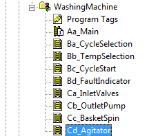
Make sure that you add JSR instructions in Aa_Main to call these routines, and make sure they call these routines in the same order they’re shown in the list.
Notice I’ve broken the low level control routines into two sections and I used “B” and “C” prefixes on the routine names to separate them. The “B” routines control the mode of the machine and provide rudimentary feedback to the person using the machine. The “C” routines control the actual machine actuators like the valves and the motion.
You already know how to add contacts, coils, branches and timers, and how to add new tags if you need to. (If you need a refresher, see the last section.) So let’s start looking at some logic to see what it does:
Cycle Selection and Temperature Selection
Similar to modes in an industrial machine, this washing machine has a cycle selection feature: Normal, Permanent Press, or Gentle. Here’s how the operator interface is supposed to work:
- Fill the machine with clothes
- Close the lid
- Select a cycle
- Press start
- When the cycle is complete, the cycle complete light turns on
- The cycle complete light turns off when you open the lid
There are also two other ways to stop the cycle: a cycle stop button, and by opening the lid. Note that in both of these cases, the machine should stay in cycle, and can be resumed by pressing the start button again. Let’s look at the cycle selection logic in Ba_CycleSelection:
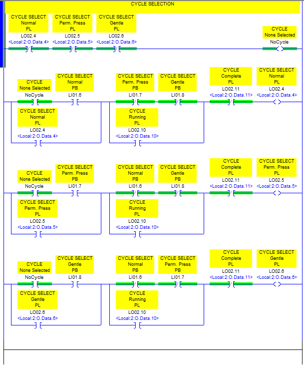
The first thing you might notice is that we’re using the cycle indicator outputs to hold the state of our cycle selection. In a large application we probably wouldn’t do this. We would use internal coils to hold our mode selection state and then drive both the indicator lights and probably the HMI indicators from those internal coils. But this is a simple machine, and this works.
We’re using a common mode selection pattern here with a “no mode” coil at the top. In order to go into a mode we make sure we’re out of any other modes first. This ensures one scan of the PLC with no mode bits energized between mode selections. Look carefully at the second rung (for the Normal Cycle). The first parallel branch gives us the condition to start the cycle (no mode, and the Normal Cycle button). We seal this in with the Normal Cycle coil itself. The second parallel branch in that rung does the following:
- If we’re not “running” yet, we can break out of Normal cycle by selecting another cycle
- It prevents the race condition where we have no cycle selected and then we press two cycle select buttons simultaneously (you can only select a cycle if you have one button of the three pressed)
- Once the cycle is “running” we can’t accidentally change cycles by pressing another cycle selection button
Finally, after the second parallel branch, we break the cycle selection when the cycle is complete. This also has the effect of preventing another cycle from being selected until someone opens the lid, which turns off the cycle complete condition.
The washing machine also has three temperature settings: Hot, Warm, and Cold. The temperature selection logic in Bb_TempSelection is identical to the cycle selection logic above, so I won’t show that here.
Cycle Start and Cycle Stop
In the logic above you saw the cycle running and cycle complete signals. These are set in the Bc_CycleStart routine:
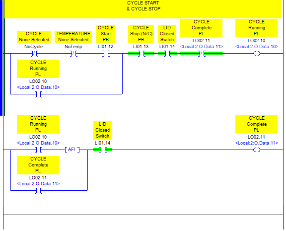
Looking at the parallel branch part of the first rung, we’re testing to see if we’ve selected any cycle and any temperature (“not no cycle” is the same as “any cycle”) and we need to see the cycle start button pressed. Once we trigger the cycle running condition, it seals in around the start button and keeps the cycle running. The rest of the rung defines our stopping condition. As we mentioned earlier, there are three ways to stop the cycle: pressing the stop button, opening the lid, or having the automatic cycle complete normally.
The second rung defines the cycle complete condition. As you can see, it only turns on when the cycle running condition is on, and it turns off when the lid is opened, but you also probably noticed that it’s incomplete. The “AFI” instruction means “always false input”. It’s like a normally open contact that never turns on. I put this in here as a place-holder because I haven’t written the logic yet that will trigger the completion of the cycle.
The AFI instruction is particularly handy for this because RSLogix 5000 will give us a warning any time it encounters an AFI. I like using these wherever I need to come back later and complete something that I wasn’t ready to complete earlier. I also use them in most output rungs when I’m writing the program so that all outputs are disabled when I download the program the first time. Then I can go through and remove the AFI instructions one at a time and test one output at a time without worrying about side-effects that might cause unexpected motion.
Fault Indicator
Like all user-friendly consumer grade appliances, we have a single indicator light that tells the owner that there’s something wrong. This logic is so complicated and perverse that I put it in its own routine just to isolate it from the rest of the logic:

Wow.
Output Rungs for the Inlet Valves
We have to go through all of our machine outputs and at least create and “stub” output rungs to get going. In most cases we won’t have enough logic ready to actually make them turn on, but we want to fill in the basic sanity check logic first, to prevent programming mistakes later from causing machine crashes (literally) or unexpected motion. When you’re starting up a machine for the first time, it’s a lot better if the machine doesn’t move when it should, rather than moving when it shouldn’t. So at the beginning, be thinking, “when should this output never turn on”?
I created a routine called Ca_InletValves for my logic to control the Inlet Valve inputs (LO02.0 and LO02.1):
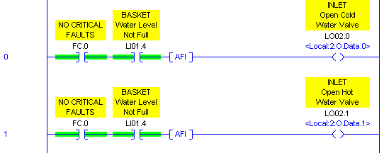
The inlet valves fill the washing machine with cold and hot water. In this case, we never want to be filling with water if we have a critical fault (the idea of a critical fault is that is should stop all actions immediately) and we also never want to be filling if the water level full sensor is on. This is a nice sanity check that prevents our sequence logic from causing an overflow if we ever get stuck in the Filling state.
I added AFI instructions here too, to act as placeholders for the auto sequence logic that we’re going to add later.
Output Rungs for the Outlet Pump
Similarly I created an output rung for the outlet pump motor starter. In this case, we don’t want to run the outlet pump once there’s nothing to pump:

Programming Motion Control for the Agitator Axis
The reason I included a motion control axis in our fictional washing machine was so I could give an example of how to program motion control in RSLogix 5000.
What defines “motion” control?
So when we’re talking about motion control, what do we mean? In general, it’s any time that your machine moves, but I don’t think that’s accurate enough. I think it’s more accurate to say that it’s any time an axis (servo, slide, cylinder, etc.) moves from one point to another point. The reason I’m being pedantic about this is because if you just have a contactor that turns on a motor and you’re not sensing some position (perhaps you’re just doing speed control) then that’s not really what we mean when we talk about motion control. However, if you start a motor and it turns a ball screw and you run it until you hit a sensor, and then you turn it off, that’s motion control (or close enough).
Whenever you see terms like Advance/Retract, Raise/Lower, Grasp/Release or Engage/Disengage then you’re talking about motion control because you have some kind of motion from point A to point B, and back again. These are simple two position motions, but it’s also expandable to 3, 4, or N positions. You can even have a position that’s calculated dynamically, like if you use machine vision to locate a part on a conveyor belt and you want to pick it up. There’s a dynamic pickup position, probably a pounce position, a drop off position, and perhaps other positions throughout your motion profile.
The Five Rung Logic Block
I’m going to demonstrate a programming pattern called five rung logic that’s applicable to all these cases. When most people first see five rung logic, they think it’s overkill. So did I. However, they have two advantages:
- They can be adapted to suit any of the above situations
- They’re a standard pattern, so other programmers who are familiar with five rung logic will find it easier to follow and troubleshoot your logic
I also found that during commissioning most of my motion control logic eventually grows to the point where it’s at least as complex, or worse, than a five rung logic block, so I discovered it’s better to just layout all your motion positions with five rung blocks at the beginning, and it makes commissioning go a lot faster.
The Five Rung UDT
The five run logic block is a great place to apply the RSLogix 5000 user defined type (UDT) feature. UDT’s are difficult to change when you’re doing online programming, so they’re not good for program structures that change a lot, but five rung logic is so standardized that you can build a UDT and use it all over the place. Here’s what a general five rung UDT looks like:
To create the UDT, go to the controller organizer, under the Data Types folder, right click on the User-Defined subfolder, and select New Data Type… Then create the following:
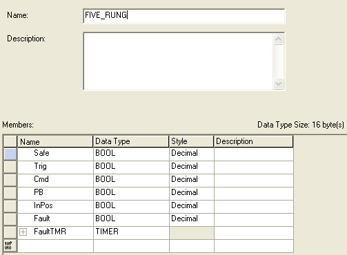
Notice I’ve added two extra things that I didn’t talk about above. One is the FaultTMR Timer. This should be obvious – if we’re going to have a timeout fault, we need a timer. The second is the “PB” tag. We may not have use of a “manual mode” on a washing machine, but every machine in an industrial automation setting will have a manual mode, and you’ll almost always want a button on your HMI that says “Move to Position A”. We include the logic for this right in the five rung block itself, so I usually like to allocate a bit for the pushbutton right in my five rung UDT.
Here’s what a generic five rung logic block looks like (note that this is only to move one axis to one position):
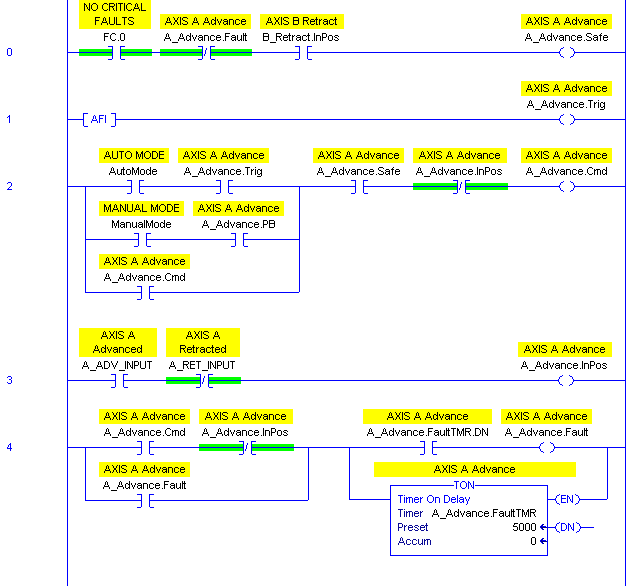
You have to customize it for each situation. The contents of the safety and trigger rungs are obviously unique, but the command rung sometimes changes depending on the scenario. You may have more than just manual and automatic modes. Some automatic actions may actually happen when you’re not in automatic mode. Sometimes you may want an axis to “jog” (for instance a hydraulic axis moves slow, and you may want it only to move in manual mode if you hold your finger on the button) and in that case, you couldn’t seal in the Command bit around the manual mode pushbutton (you’d just seal it in around the trigger contact).
In a simple case, you would take the Command coil and use it to drive your Advance output, whether it be a solenoid, or whatever. In our case, we have a servo axis. This means we need to use RSLogix 5000 motion control blocks.
We need two motion blocks for each position we want to move to: an MAM instruction (motion axis move) and an MAS instruction (motion axis stop). The MAM instruction makes us go, but the MAS instruction let’s us stop motion when we need to abort it:
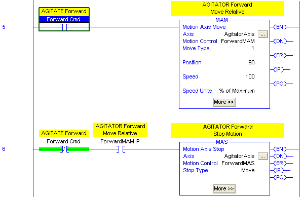
Notice that the MAM instruction has a Move Type parameter that I set to 1. This means it’s an incremental move. There are more options than just absolute and incremental. Check the MAM instruction help (highlight the MAM and press F1) to see a description of these options. Since I’m using a rotary axis here, I’m giving my command in degrees, so this instruction tells the axis to move 90 degrees forward from where it is now.
I’m just using the Command coil from my five-rung logic to drive the motion here. If the MAM instruction completes the move, it will turn on the .PC bit (program complete?). However, if it doesn’t complete (and the Command coil drops out before it completes), then the second rung will detect that the motion is in progress (the .IP bit) and will execute the MAS instruction to stop the move command.
For an incremental move, it’s reasonable to use the .IP bit from the MAM instruction in the “In Position” (or “Complete”) rung of your five-rung logic block. However, when doing absolute moves to a fixed position, I find it more reliable to base my In Position logic on the following axis tags:
- .ActualPosition
- .PositionLockStatus
- .AxisHomedStatus
That is, you can take the axis’ actual position and compare it against some limits you set to denote your position (plus or minus a tolerance). The position lock status tells you that the axis is within the position limits set in the axis configuration. You need to take the axis homed status into account before you even look at the actual position tag (normally the position won’t be valid if you haven’t homed). Homing is a lesson for another tutorial or blog post, but I’ll give you a hint: MAH.
Whew… that was rather long. Now it’s on to the sequence of operations…
I noticed that you have alias labels showing up on all your i/o bits for the inputs referenced in these programs. Because we didn’t alias the tags from the input card directly (we use an XIC bit to examine each input and store their state in an OTE) the alias is not showing up for me. I can’t change it manually so my question is, how did you get them to show up?
This is a very helpful tutorial and I appreciate the time you spent creating it. Thanks!!!
@Bob: Actually only the output bits are aliased to “real” output tags. The inputs bits (LI…) are created with OTE instructions as you say, and do not have alias tags beneath them.
Ahh… my problem was I did not alias the LO02 bits to the output card upon creation of the tag. I just noticed that your program had aliases showing up and mine did not have any, overlooking the fact that they were all outputs. I’m a little new at this 🙂
Thanks
@Bob: Hey, no problem! Glad to help, and thanks for the words of encouragement!
Thanks for this tutorial! I have fiddled with RSLogix 5000 over a few years but never been involved in a real project. I come from the SLC 500 world. This has been very helpful, especially knowing that ControlLogix is asynchronous. I am now involved in a ControlLogix project trying to repair some bad code. Your tutorial has helped me understand the previous programmer’s intentions. I did not understand from your tutorial that the data type for the tag A_Advance needed to be FIVE_RUNG. I eventually figured it out.
Keep up the excellent work!
hi
newbie at plc.
question about “seal-in”. i’m confused with when and how it works.
like on the example of ladder, “A_advance.cmd” at rung 2 or “A_advance.fault” at rung 4, if they’re not “or” with running condition, what’ll happen??
what’s the big difference between sealed-in output and not-sealed-in output??
@john – A seal-in is like a flip-flop circuit in electronics, or a memory bit in a computer. It holds its value. If you didn’t include the seal-in circuit around the .Trig bit, then the .Cmd output would just pulse on momentarily, and wouldn’t stay on for the duration of the motion. Likewise with the .Fault bit, you want that bit to stay on until someone clears it.
In the cycle selection logic above, how is the program going to identify “CYCLE None Selected No Cycle’coil? I can’t see its bit location in the plc memory. Thanks for this tutorial. It is far much better than school.
@william – when you define a BOOL tag (NoCycle), the program allocates space in the PLC memory for that value. You don’t address it directly, so it’s more like a variable in traditional programming languages. The controller handles that implementation details.
Does this apply for the ‘çycle running PL’ too? I was expecting a rung with N/O contacts for normal, gentle and perm all ‘ORED’ to each other Ãn a branched rung to control a coil for “cycle running PL. If this is not the case, how then does the cycle running contact recognize that one of the three options is selected? i thought it should be associated with an internal coil that triggers its change of state each time either normal, gentle or perm is selected. What do you think?
@william – it’s a 2-step process to start the cycle. First you select which cycle you want, then you press the cycle start PB. The rung for Cycle Running PL says that you have to have selected a cycle type, and then you have to press the start PB. Then the cycle runs until a stop condition happens.
where do you create the five rung logic? Do you create a new program under ‘task’or a new routine under ‘main task’?
@william – it’s up to you, but I generally put two related five-rungs together in their own routine. For instance, if I had a cylinder with 2 motions (extend/retract), I’d have one five-rung logic group for each motion, and I’d put them both in a routine named for the cylinder (or axis). With a servo (continuous position) I generally have five-rung logic groups for each logical position (pounce position, pick-up position, drop-off position, etc.). I would put them all in a single routine, but there are cases where you might want to break them out each into their own routine. It’s all about how you want to organize your code.
Scott,
I also come from the SLC 5/03; MicroLogix background.
Viewing your tutorial was VERY helpful. I have inherited a RSLogix 5000 installation where the previous SSI “did_use_the_really_long_tagnames” that you referenced in your tutorial.
I much prefer N9:0; F10:12; N10:2/3, etc. As you say, the “conciseness” is easier to work with. So, now as I’m adding a new Sewer Lift Station to the existing system, I utilized your suggestion: “Buda Elementary School Lift Station Digital Inputs” became – “BES_LS_DI[0] A lot cleaner and easier for an “old dog” to learn these “new tricks”.
Thanks again, well done.
Ben Gray
Central Texas Water Maint.
Nice Work. I had heard about PLCs while I was graduating from high school five years ago and as a huge fan of instrumentation engineering. I find this article impressive but I’m very new to whole PLC programming thing, I really need you to refer me to a site where the Agitator tags were discussed in detail. To me, the addressing and programming of the Input and Output Cards looks straight forward but I’m really struggling to understand the concepts behind the agitator tags such as (ActualPosition, PositionLockStatus, AxisHomedStatus). The problem is that we’re required to be well conversant with this terms to get jobs but no employer is willing to train and that’s I thank you. Hope to hear from you soon. Sorry my comment is so long
@Scott, first off this has been an outstanding tutorial for a guy coming from a SLC500 world. The differences are easy to follow, and I appreciate your pre-planning to build a solid structure and foundation, as well as explanations as to why you organize things the way you do. That can be a bit of an overwhelming difference between RSLogix 500 and RSLogix5000. So, thank you.
You lost me at the five-rung instruction part. I understand the concept, but I didn’t understand how you incorporated that into the washing machine program. Your five-rung ladder uses tags we are obviously not using here, but your two rungs for the agitator pick up at rung 5 and rung 6, so it would appear that they are in the same ladder as the five-rung routine right above it. I see you using the UDT for the agitator logic, but I got lost trying to figure out how to incorporate the five rung ladder with the agitator.
@CevinMoses – I guess you’re right, the 5-rung picture is just a generic 5-rung block that I threw in there, and it’s for an Advance motion. The agitator needs a Forward motion and a Reverse motion. So the Safe rung would be Axis Ready and no faults. The Trigger would be driven by the sequence logic (defined elsewhere). There would be no ManualMode branch in the Command rung, but there would be a Cycle branch of some kind to indicate what cycle the washing machine was in. For the In Position rung, I typically use some combination of the ForwardMAM.IP and ForwardMAM.PC bits. The .IP bit comes on while it’s moving (in progress) and the .PC bit comes on when the motion completes. You could just use a rising edge on the .PC bit, capture the axis position, and keep the In Position sealed in as long as the axis stays within some tolerance of that position. Alternatively just keep it sealed in until you command it to go in Reverse (since this is such a simple machine). It will depend on your circumstance, really.
In case anyone is interested, here’s a link to the Logix5000 motion control instructions. It tells you all about things like the .IP and .PC bits. Very helpful for understanding what’s going on.
Hi
I lost from creating data types.Did you craete the new tags in the five rung individually or they are automatically created after creating the UDT.
@andrew: if you have a FIVE_RUNG UDT defined, and then you create, e.g., a tag named A_Advance with the type of FIVE_RUNG, then that’s all you need to do. All of the sub-elements will be created for you. You can also nest UDT’s inside of other UDT’s to create a tree-like hierarchy. However, be aware that editing a UDT requires a download of the program, which can be a big pain. Therefore, only use UDT’s to define data structures that won’t change when you’re in the field. That is, don’t use them to define your logical machine structure, like Drive1.Motor.Run. You’re better off with Drive1_Motor_Run, because it’s more flexible if you have to make changes when the machine is running.