This is part of an RSLogix 5000 Tutorial.
In a ControlLogix (or CompactLogix) processor, your logic is divided into tasks, which are then divided into programs. These terms will be very familiar to you if you have a good understanding of real time operating systems, but might be confusing to you if you just graduated from a SLC 500.
In this tutorial I’m just going to setup something that mimics what you’ll be used to from the PLC/5 or SLC 500 world. We’ll create one continuous task. There can only be one continuous task, and it’s the lowest priority task in the controller. That means the motion, communications (with I/O, etc.), user defined periodic tasks and event tasks will all preempt the continuous task when they run. The continuous task runs all of its programs, and then it starts again (continuously, you might call it). It’s quite normal to put most or all of your logic in the continuous task.
While I won’t get into creating them here, periodic tasks are scheduled to run at a pre-defined period, such as every 100 ms. Event tasks are scheduled to run at specific times, like on startup.
When you look at your controller organizer tree, you’ll see a Tasks folder that looks like this by default:
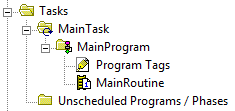
RSLogix 5000 has already created a continuous task called MainTask for you. Note the little circular arrow on MainTask – that means it’s a continuous task. Inside MainTask, it’s created a program called MainProgram, and it has one ladder logic routine called MainRoutine inside. It also has a place for program specific tags. These are tags that are only visible to logic inside of this program.
Programs are the main way to organize your project on a macro level. If you were programming an assembly line with 5 cells, it would make sense to put the logic for each cell into its own program. Likewise, if you were just programming a single cell with 5 stations, it would make sense to put each station into its own program. This is a decision you have to make based on your own needs. It’s also normal to move non-control logic, like communications, HMI interfacing, mapping inputs, and mode selection into their own programs so they don’t clutter the control logic.
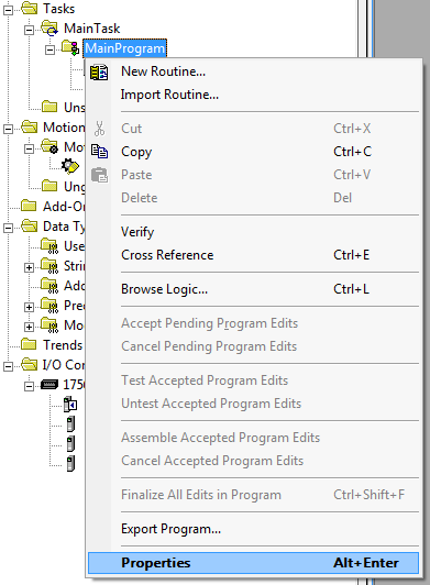
Let’s start by changing the name of “MainProgram” to our first program, “MapInputs”. Right click on the MainProgram and select Properties from the context menu:
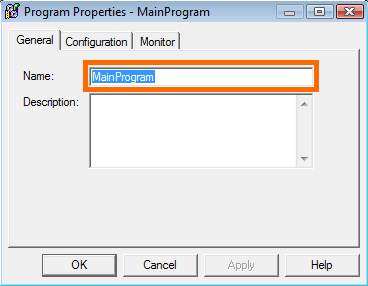
That will display the Program Properties dialog box. You can edit the name here (highlighted below). Change it to “MapInputs”, then click OK:
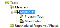
Once you’ve clicked OK, you’ll see the program name has changed in the controller organizer:
Now we want to add the following other programs to this task: “Faults”, “Global”, and “WashingMachine”. Let’s start by adding “Faults”. Right click on MainTask, and click New Program…:
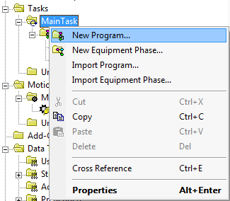
That will display the New Program Dialog. Enter the name Faults in the Name field, and click OK:
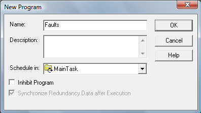
Repeat the same process for two more new programs: Global and WashingMachine. When you’ve finished, you should see this in your controller organizer:
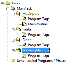
That’s all there is to adding programs. I’d like to show you one more thing before we move on to laying out the routines: you can rearrange the programs within a task, or even remove or add programs to a task. Start by right clicking in MainTask in the controller organizer and clicking Properties:
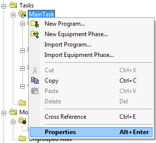
That will open the Task Properties Dialog. Click on the Program/Phase Schedule tab (highlighted at the top of the image below):
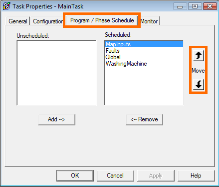
The listbox on the right is the list of programs that are assigned to the task. You can select programs in this light and use the Move up and down arrows (highlighted) to change the order in which the programs are executed inside this continuous task. The programs will show up in the controller organizer in this same order (which is intuitive).
You can also remove programs from execution using the Remove button below the listbox. This is a useful feature, for instance, if you want to disable execution of the MapInputs routine while you’re bench-testing the program without real I/O attached. Then you can just toggle your input bits and watch the program execute.
In the next part of the tutorial, we’re going to get into how to layout routines in a logical way within each program.
Thank you. A++ info for experienced or beginner.
Thanks a lot. Wonderful job…
good job
Excellent, continue
“Event tasks are scheduled to run at specific times, like on startup.”
Actually they are not scheduled at all. The trigger for an even task can be hardware driven or software driven with no basis in time. That’s what the periodic tasks are for.
While an Event task can be made to run if configured for “EVENT Instruction” and then put on the end of a rung with an XIC of the S:FS tag, this isn’t typically done.
Wonderful and clear explanation! I will keep going on to learn. Thanks a lot!
Dear sir,
Pls make a ladder diagram logic for high level controll in Rs – Logix – 5000
” When the High level input reaches then it should generate a output in Auto to close the gate”.
I appreciate how a lot of this is not washing machine specific, but is more of a common layout for most applications. Out of curiosity, what is the Global task used for?
@CevinMoses – You are correct that this is a layout that supports a larger system. The CompactLogix processor is actually quite capable of running a whole assembly cell, or even a small assembly line by itself. Typically an automation cell will be broken into stations, possibly numbered in order, like Station 1, Station 2, or possibly by “operation” like OP10, OP20, etc. You also might have more functional names like Load Station, Weld Station, and Unload Station.
The idea of the Global program is to be a place to put stuff that affects the whole cell or whole line, such as interfacing with the Controller real-time clock, interfacing with a cell safety system, or monitoring utilities such as air, water, fuses, etc.